*LOAD_NODE_SET
Applies a concentrated nodal force to a set of nodes.
Card
NSID = the set of nodes where the force is applied.
DOF = 1, 2 or 3 depending on the force direction x, y or z.
LCID = ID of the load curve that describes the magnitude of the force (see *DEFINE_CURVE ).
SF = 1.0 (default), load curve scale factor.
CID = ID of local coordinate system used. Set to 0 for the global coordinate system.
*LOAD_RIGID_BODY
Applies a concentrated nodal force to a rigid body. The force is applied at the center of mass.
Card
See *LOAD_NODE_SET. Note that parameter NSID is replaced by PID which is the ID of the part the force is applied to.
*LOAD_SEGMENT_SET
Applies a distributed pressure load over each segment in a segment set.
Card
LCID = ID of the load curve that describes the magnitude of the pressure (see *DEFINE_CURVE ).
SSID = ID of set of nodes to which the pressure is applied.
SF = 1.0 (default), load curve scale factor.
AT = arrival time for pressure is assigned the time at load step 1 if pressure is given in tabular form or 0 if constant pressure.
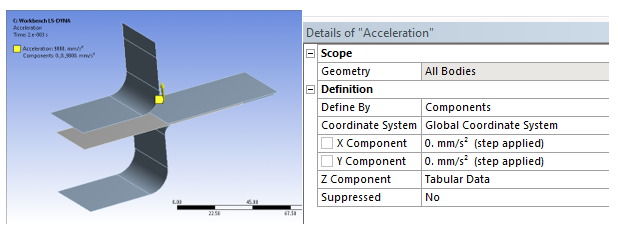
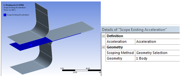
*LOAD_BODY_PARTS
By Default Acceleration or Gravity load are applied to all bodies in the model, and it is sometimes convenient to apply these loads to only a portion of the model. *LOAD_BODY_PARTS is used in that context.
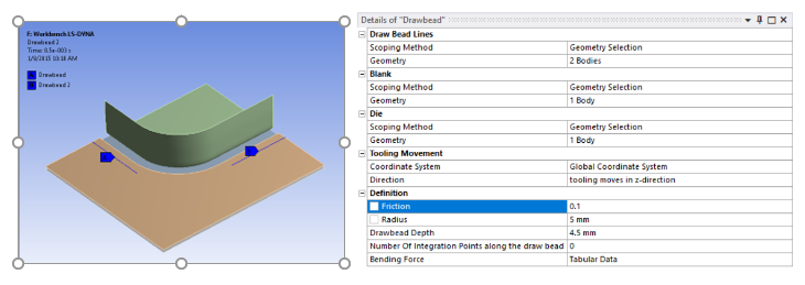
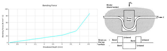
*DEFINE_BOX_DRAWBEAD
*CONTACT_DRAWBEAD_ID
These two keywords are used to support Drawbead modeling. Drawbeads are used to control the flow of sheet metal into the die cavity during stretch-draw forming of large panels. LS-DYNA enables them to be defined them through a specific contact algorithm.
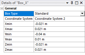
*DEFINE_BOX
Define a box-shaped volume. Two diagonally opposite corner points of a box are specified in global or local coordinates. The box volume is then used for various specifications for a variety of input options, such as velocities, displacement, and so forth.
Card
Box ID = ID of the Box object
XMN = Xmin
XMX = Xmax
YMN = Ymin
YMX = Ymax
ZMN = Zmin
ZMX = Zmax
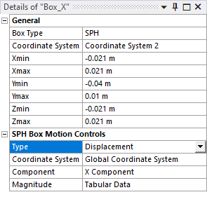
*DEFINE_BOX_SPH
Define a box-shaped volume. Two diagonally opposite corner points of a box are specified in global coordinates. Particle approximations of SPH elements are computed when particles are located inside the box. The load curve describes the box motion as function of time.
Card 1
Box ID = ID of the Box object
XMN = Xmin
XMX = Xmax
YMN = Ymin
YMX = Ymax
ZMN = Zmin
ZMX = Zmax
Card 2
VID = Vector ID created from Component using *DEFINE_VECTOR
LCID = Load curve ID created from Magnitude tabular data using *DEFINE_CURVE
VD =
0 if Type = Velocity
1 if Type = Displacement
*DEFORMABLE_TO_RIGID
In some dynamic applications, long duration, large rigid body motions arise that are prohibitively expensive to simulate if the majority of elements in the model are deformable. One such example would be an automotive rollover where the time duration of the rollover would dominate the CPU cost relative to the impact that occurs much later. To improve efficiency for this class of applications, The LS-DYNA system offers the capability to switch a subset of materials from a deformable state to a rigid state, and then back to deformable. By switching the deformable parts to rigid during the rigid body motion stage, you can achieve significant savings in computation time.
Deformable/rigid switching is inherently related to performing a restart. You need to stop the analysis, define the part switch, and then restart the analysis again.
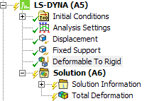
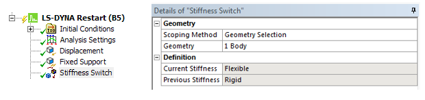
The scoped body is defined with flexible material properties. It is switched to rigid for the first calculation.
*RIGID_DEFORMABLE_D2R
The body stiffness can then be modified in dependent calculations. If the stiffness was rigid, it is switched to flexible
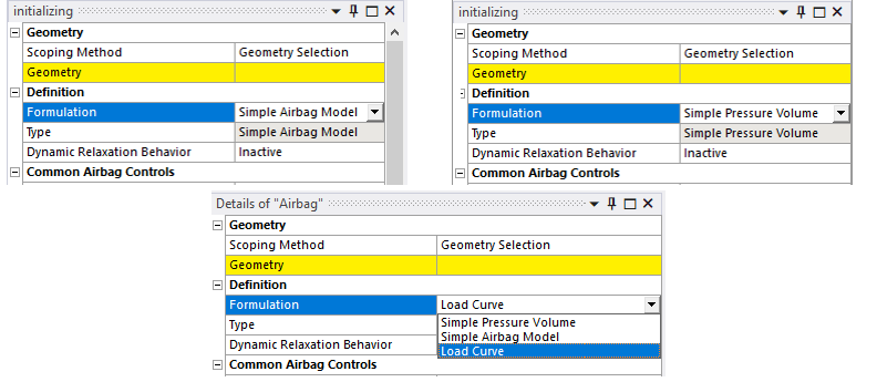
*AIRBAG_SIMPLE_AIRBAG_MODEL
*AIRBAG_SIMPLE_PRESSURE_VOLUME
*AIRBAG_LOAD_CURVE
These three keywords are used to support airbag modeling. Set the type to Simple Airbag Model, Simple Pressure Volume, or Load Curve, respectively. See Airbag or Simple Pressure Volume for more information about using the airbag object.