Files required:
5_4_1_App_MF.zip: Download
Unit System:
mm-second-tonne-Newton
Files required:
5_2_App_Airbag_Folding.zip: Download
Click in the right toolbar.
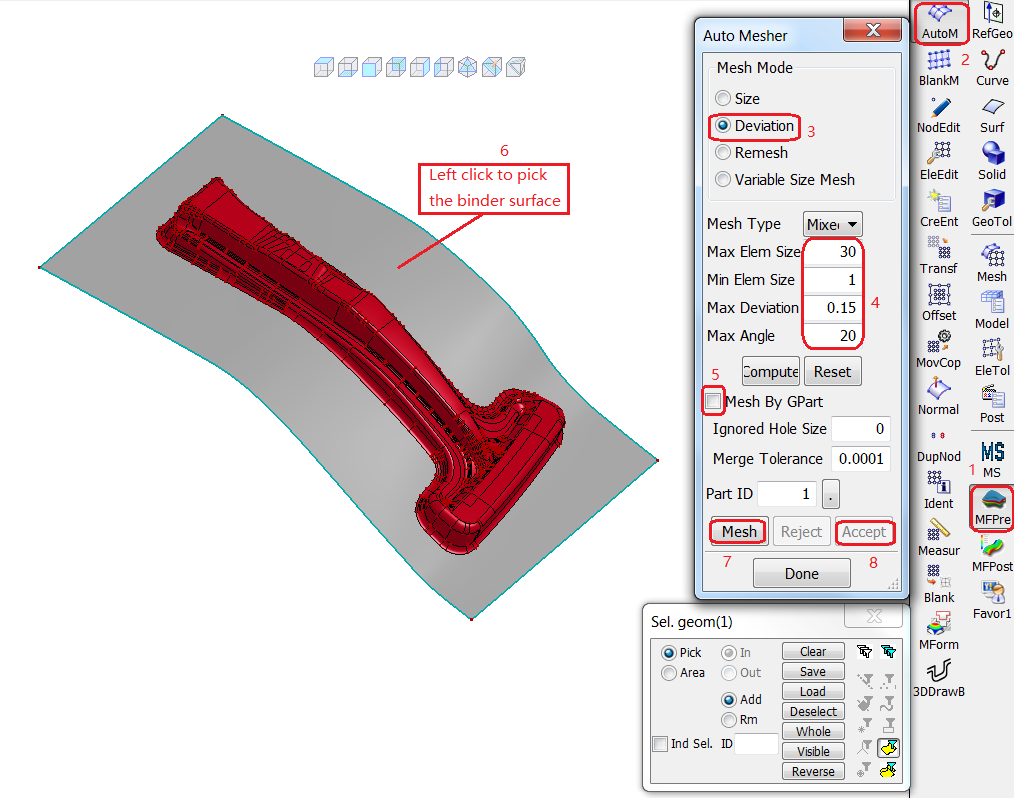
Click in the MFPre toolbar to open the Auto Mesher dialog.
In the Mesh Mode section, select Deviation.
Enter the following meshing options:
Max Elem Size =
30.Min Elem Size =
1.Max Deviation =
0.15.Max Angle =
20.
.
If it is activated, clear the Mesh By Gpart check box.
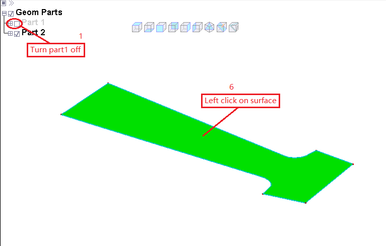
In the Graphics Window, click the binder surface to pick it.
Click .
Click .
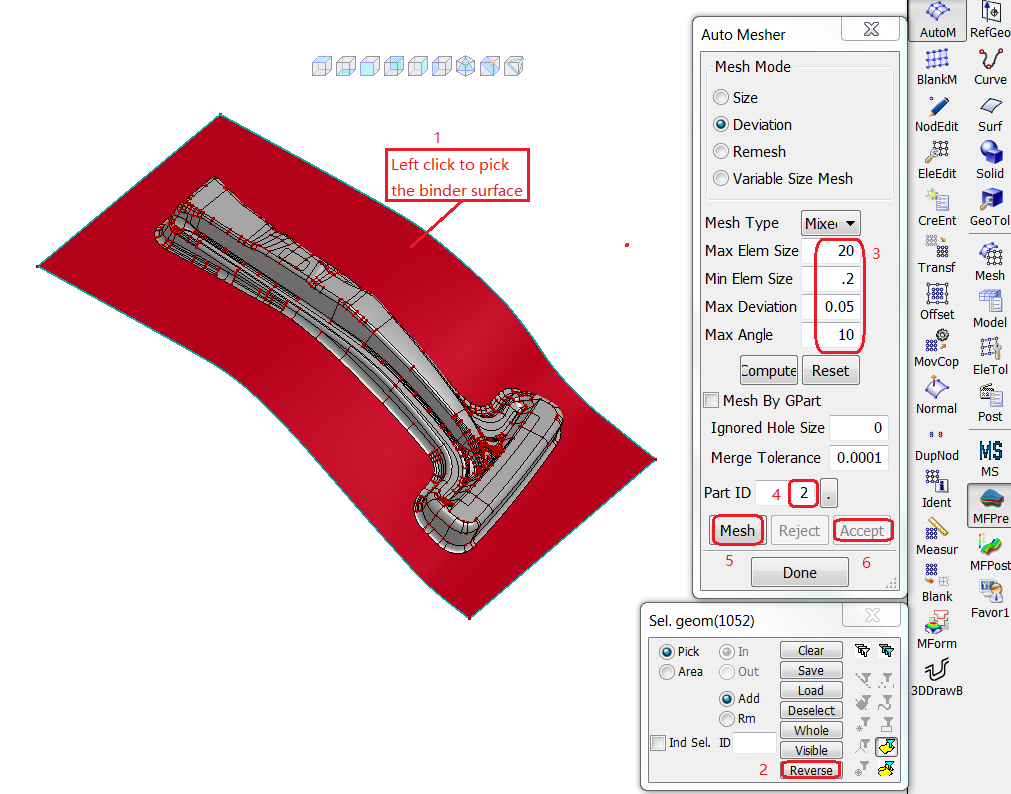
In the Graphics Window, click the binder surface to pick it.
In the Select geom dialog click to invert the selection.
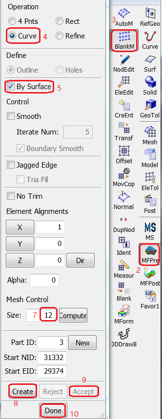
Enter the following meshing options:
Max Elem Size =
20.Min Elem Size =
.2.Max Deviation =
0.05.Max Angle =
10.
.
Click the . button next to and select part ID .
Click .
Click .

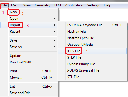
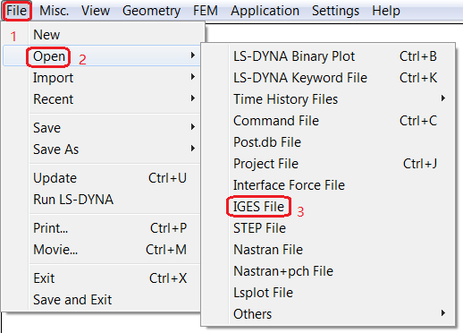
Choose > > > from the menus.
Open Numisheet08-BM03-Blank.igs file.