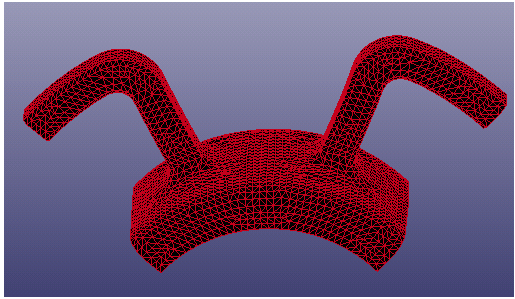
In this tutorial, you will create surfaces from a complex mesh model using the Surface from Mesh option. The original mesh model is shown in the following picture.
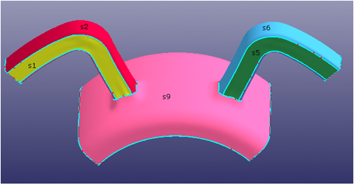
Create 12 surfaces from the mesh model. They are shown in the following two pictures. From the pictures, you can see the surfaces' boundary lines extending along the natural mesh feature line. You will select the elements using the Propagation method for reasonable feature line boudanry capturing, and view some details for better surface generation.
This tutorial uses the Keyword file multisurf_frommesh.k. In the pulldown menu, go to File > Open > LS-DYNA Keyword File, choose multisurf_frommesh.k.
Create surface S1. First, click the bottom toolbar icon to set the element displaying mode as Hide Elem. This mode enable users select the element easily. Then,
click > >
or click the left icon
. Select the check box Prop and set the Ang
parameter to
10. Select the highlighted elements in the
following picture.
These elements capture the fillet feature line on both sides of boundary. The boundary line is very similar to a rectangle since there are 4 right angles (tagged by green circle in the picture). Therefore, check Untrimmed boundary in the dialog and create the surface as untrimmed surface (surface boundary is iso-line).
Untrimmed surface has more advantages of matching with neighbor surface on the boundary line to G0/G1 continuity in math than trimmed surface since untrimmed surface boundary line is iso-line while trimmed surface boundary line is not iso-line.
If you do not check Untrimmed boundary, the surface will generate a trimmed surface as shown in the following picture. However, the untrimmed surface is better for this tutorial.
After you have gotten a satisfactory surface, such as the precision is smaller than 0.01, click to add the surface into database, then click the check box Mesh again for another new surface generation.
Continue to create surface S2 to S8 by using the same element selection method in step 1. When you select elements, pay attention to keep the surface boundary smooth enough for being matched with new surface S9 later.
Continue to create surface S9. Select all the highlighted elements shown in the
following picture by setting Prop Ang = 10.
Continue to create surface S9. Select all the highlighted elements shown in the
following picture by setting Prop Ang = 10.
Make sure that you have selected all the neccessory elements. In the following picture, there is one triangle element (in green circle) lost in the selection. This lost element will result in a hole in the surface, or sometimes, if this element happens on boundary position, the surface may not be created successfully due to self-interstionc boundary line happening there.
Continue to select all the neccessory elements for surface S9, and make sure the surface boundary has been matched the original surface's boundary very well.
Set Max tol = 0.01. Uncheck Untrimmed
boundary since you can accept the trimmed surface here. Click
for base surface and click
for advanced surface to create surface S9.
Create surface S10 by setting Prop Ang = 10 for element
selection, unchecking Untrimmed boundary, and setting Max tol =
0.01.


