 The Seam Weld Connectors option allows you to create bar elements from all nodes that lie on the specified curve to a specified surface. The created connectors will be normal to the surface, so the surface elements may be automatically split in order to create nodes at the proper locations to connect the bars. If nodes are aligned around the seam within a tolerance, then the elements will not be split.
- Seam connector name
The part name is generated automatically, starting with SEAM_CURVES0.
- Weld type
Point to point
creates a row of bar elements between the nodes of the source curves and the nearest nodes of the target surface mesh.
Curtain tris/quads
creates quad elements with some tri elements in between the nodes of the source curves and the nodes of the target surface mesh. Curtain welds are generally intended to be defined on single edges to close a gap between two parts.
Note: In many cases, extending surfaces by using Geometry > Create/Modify Surface > Extend Surface > Close gaps Between Midsurfaced Parts is a more robust way of ensuring the creation of shell elements to represent the connection between parts.
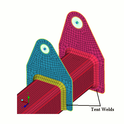
Tent
is a specialized method that creates curtain elements with additional tent elements and defines particular meshing parameters on the source curves. The geometry is modified by surface extension or curtain surface functions. The Tent welds extend the surfaces to intersection and then diagonal quads represent the fillet welds.

- Tent Weld type
select either T welds or Lap welds.
- Diagonals
For T welds, diagonals can be added to the Positive or Negative directions, or both. For Lap welds, diagonals can be added only to either the Positive or Negative directions.
- No. layers
number of quad rows along the welds.
- Tent weld spacing
Distance to Weld Toe
The weld spacing can be determined by specifying the Distance to weld toe, the Number of layers to toe, and the Growth ratio after weld parameters.
Weld fillet radius
The weld spacing can also be determined by specifying the fillet radius of the weld.
- Source curves
specifies the curves representing the edge of surface to be seam welded to the target surface.
Note: The source curves information may not be retained when you try to modify an existing seam weld connector.
- Target part
specifies the surface part to which the connectors will attach. The connectors will be normal to the surface. Since new nodes are projected, the surface elements must lie on top of a surface, and they must be in the same part as the surface.
- Max projection
is a value slightly more than the distance between the source entity and the farthest target surface.
- Part name
The connector part name is automatically generated, starting with SEAM_WELD0.
- Element splitting
Remesh area (Tri/Quad)
remeshes the area of the seam weld after computing the mesh and connector.
Terminate
terminates the split to keep the mesh count down. It doesn’t give as many high aspect ratio quads, but it creates many tri elements.
Propagate
propagates the split through the mesh until the propagation is stopped by a tri element or it exits to the ORFN region.
Note: This may result in new quad elements with poor aspect ratios.


