 The Feature Detect Bolt Holes option detects single edged connected regions in a part whose diameter is between the defined min and max values. When a bolt hole is detected, the following occurs:
The bolt hole curves are either placed in a subset (if Settings > Geometry Options > Inherited part name is set to Inherited), or placed in the defined part name (if Settings > Geometry Options > Inherited part name is set to Create New).
The curves that are marked as bolt holes have the mesh parameter settings modified to the defined Number of quad layers and height ratio (Ring offset ratio). If smart sizing is used, the mesh size will also be adjusted as defined in the note below.
- Curves to check
The bolt hole detection will be run on the selected curves. If no curves are selected, the bolt hole detection will be run on the entire model.
- Num quad layers
The number of quad layers of uniform height to be grown from the hole. This is equivalent to the Tetra Width mesh curve parameter.
- Ring offset ratio
An expansion ratio from the first layer of elements on the curve. This ratio will be multiplied by the element height of the previous layer to define the next layer. You can enter any positive real number. This is equivalent to the Height Ratio mesh parameter.
- Min / Max diameter
Bolt holes with diameters within this specified range will be found.
- Remove holes below min
If the min diameter is set larger than holes you want to remove, then this option will remove all holes smaller than the Min diameter.
Note: It is recommended that mesh sizes be set before using this feature, as the offset layers require the mesh size of the curves to be set properly.
If the mesh size and Num quad layers are defined, the smart sizing will try to decrease the mesh size so that the defined mesh size is obtained at the top of the quad layers rather than at the bolt hole. The smart sizing function calculates the ratio of the original mesh size at the outer ring of the quad layers to the new mesh size and reduces the original mesh size by this ratio.
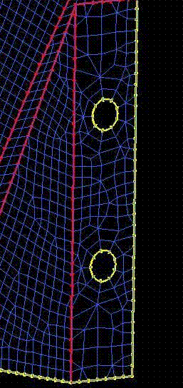
In the example below, bolt holes without smart sizing are shown. Uniform mesh spacing was set on all curves prior to bolt hole detection.
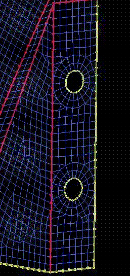
An example of bolt holes with smart sizing is shown below, with the same original uniform mesh spacing.
Note: If you run bolt hole detection multiple times with smart sizing, the mesh size will be reduced each time. Smart sizing uses the current mesh size to compute what the new size should be. To avoid excessive refinement, it is recommended that this feature be run only once, or redefine the nominal mesh size on the curves before running bolt holes a second time.


