To edit properties of an assembly item, use the following procedure:
Click on the
 button in the Object modification toolbar or right-click the assembly item in the Model
manager window and select Edit in
the drop-down menu. This will open the Assemblies panel (Figure 9.64: The Assemblies Panel (Definition Tab) and Figure 9.65: The Assemblies Panel (Meshing Tab)).
button in the Object modification toolbar or right-click the assembly item in the Model
manager window and select Edit in
the drop-down menu. This will open the Assemblies panel (Figure 9.64: The Assemblies Panel (Definition Tab) and Figure 9.65: The Assemblies Panel (Meshing Tab)).
Change the description of the assembly, if required, in the Info tab of the Assemblies panel. Changing the description of an assembly is the same as changing the description of an object. See Description for details.
Change the graphical style of the assembly, if required. Changing the graphical style of an assembly is the same as changing the graphical style of an object. See Graphical Style for details.
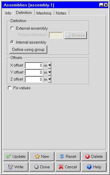
In the Definition tab, select the assembly to be added to the model (Figure 9.64: The Assemblies Panel (Definition Tab)). There are two options:
External Assembly enables you to use an assembly that was created in a previous Ansys Icepak session. Specify the name of the project where the assembly was created in the Project definition text entry field. You can enter your own filename, which can be a full pathname to the file (beginning with a / character on a Linux system or a drive letter on Windows) or a pathname relative to the directory in which Ansys Icepak was started. Alternatively, you can choose a filename by clicking on the square button located next to the Project definition text field and then selecting the file in the resulting File selection dialog box. See File Selection Dialog Boxes for more information on the File selection dialog box.
Note: When you use the external assembly option to define your assembly, the assembly is not copied into your model. Ansys Icepak creates a link to the project that contains the assembly. To copy the assembly into the model and store it in the model, you should create the link to the external assembly using the External Assembly option as described above, then select the Internal Assembly option and click Update. If the external assembly is not copied into the current model, all modifications made to the external assembly will be lost.
Internal Assembly enables you to specify a group that is defined in the current model to be used as an assembly. This option is selected by default. To specify a group, click the Define using group button and choose a group from the list in the subsequent Selection panel.
(optional) To translate the assembly by a specified distance from its original position, define the distance of the translation from the original position by specifying an offset in each of the coordinate directions: X offset, Y offset, and Z offset.
Note that if you want to perform a transformation that is different from that provided by the Assemblies panel, you can create an initial assembly and then perform additional transformations using the Move assembly panel. The Move assembly panel is identical to the Move all objects in model panel described in Resizing the Cabinet and Repositioning the Cabinet. You should also note the extra details for moving an object in Repositioning an Object.
Note: If you scale, rotate, mirror, or translate the assembly, these operations will be performed with respect to the assembly’s local coordinate system and not the global coordinate system.
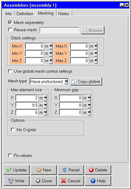
In the Meshing tab, specify whether you want to have the assembly meshed separately from the rest of your Ansys Icepak model (Figure 9.65: The Assemblies Panel (Meshing Tab)).
To allow Ansys Icepak to generate a non-conformal mesh, turn on the Mesh separately option. See Generating a Mesh for details about generating a mesh.
To reuse mesh already generated for an assembly from another project or an external mesher, select Reuse mesh. Select Browse to select and import the mesh file. In order for mesh to be reused, the assembly geometry from the source must be identical to the assembly's geometry (object names and types can differ, however). Overlapping mesh cells are sorted according to the current object priority settings.
Note: A mesh imported as solid can be made hollow if the object's properties are set to hollow. Hollow object mesh cannot be made solid since no new mesh cells are generated in the process.
Note: If your project contains multiple instances identical assemblies, you can reuse the same mesh for each assembly. The mesher automatically translates the imported mesh. Rotation of imported mesh is not supported.
The following mesh formats are compatible:
Icepak mesh (grid_output file)
Fluent mesh (.msh)
If you selected Mesh separately, specify the Slack settings distance around the bounding box of the assembly (Min X, Max X, Min Y, Max Y, Min Z, Max Z). The bounding box will be moved outward by the amount of slack that is specified. Additionally, each of the slack distances can be assigned by aligning the edges of the assembly bounding box to existing edges of objects or other assemblies. To do so, follow the procedure described in Aligning an Object with Another Object in the Model.
For example, to set the slack distance in the Min X direction, you would first click Min X displayed in orange in the Meshing tab of the Assemblies panel, then click the edge of the object in the graphics window that you want to align with the Min X edge of the assembly bounding box.
If you selected Mesh separately, you can deselect Use global mesh control settings to enable Max element size, Minimum gap, and Options. If Use global mesh control settings is selected, the mesh control settings will be inherited from the global mesh settings. Click Copy global to populate the mesh control settings with the current global mesh setting values.
If you deselected Use global mesh control settings, you can specify the Mesh type for the objects in the assembly. Assemblies meshed separately can have a mesh type different from the type used to mesh the outside assembly.
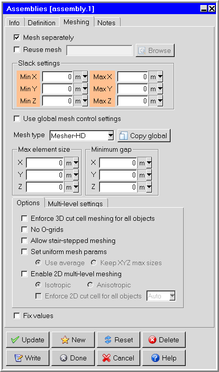
By default, Ansys Icepak uses the same mesh type specified in the Mesh control panel to mesh the objects inside the assembly. If the Mesh type is Mesher-HD, the Meshing tab will appear as shown in Figure 9.66: The Assemblies Panel Using Mesher-HD (Meshing Tab).
If you deselected Use global mesh control settings, you can specify a limit on the element size of the assembly mesh in the x, y, and z coordinate directions. To do so, select Max X, Max Y, and Max Z size specifications and set each one to the desired maximum element length in each direction.
If you deselected Use global mesh control settings, you can specify the Minimum gap that separates objects in the assembly in the X, Y, and Z directions. This specification is used by Ansys Icepak whenever the distance between two objects inside the assembly is less than this value, but greater than the model’s zero tolerance.
If you deselected Use global mesh control settings, you can select No O-grids to allow no O-grids to be specified on a per assembly basis.
A brief description of options available with Mesher-HD is given below. These options are available when Use global mesh control settings is deselected. For more detailed information, see Global Refinement for a Hex-Dominant Mesh.
Note: When enabled, the options on the Options and Multi-level settings tabs are applied only to the selected assembly, overriding the global mesh settings in the Mesh Control panel. Select the check box on the left to enable the corresponding local mesh setting. When disabled, global mesh settings in the Mesh Control panel are applied.
Enforce 3D cut cell meshing for all objects enables 3D cut cell meshing instead of the mesh settings selected in the Misc tab of the Mesh control panel.
No O-grids allows no O-grids to be specified on a per assembly basis. This option can be found in the Options tab.
Allow stair-stepped meshing and Allow multi-level meshing can be activated in the Options and Multi-level settings tabs when Mesher-HD is selected.
Set uniform mesh params is best used with multi-level meshing. This option can be found in the Options tab.
Set uniform mesh params has two options: Use average and Keep XYZ max sizes. Use average creates a uniform mesh with the same mesh size in all coordinate directions. The mesh size is computed by averaging the specified max element sizes. Keep XYZ max sizes creates a uniform mesh in each coordinate direction using the corresponding max element size. The resulting mesh has constant spacing in each coordinate direction but the spacing can be different if the max element sizes are different. Using uniform mesh params results in lower mesh count and improved quality. It is recommended to use uniform meshing params when multi-level meshing is used. If this option is enabled then 3D cut cells and stair step meshing ignores the object-based params to keep the mesh uniform and generates better quality meshes. To provide object-based control on meshing, meshing levels can be used for the objects defined under Edit levels.
Enable 2D multi-level meshing starts with a coarse background meshes and then refines the mesh to resolve fine-level features. Lastly a 3D cut-cell technique is used for fitting the mesh.
Anisotropic refinement enables you to refine the mesh in adapting to the geometry. This option yields lower cell count but quality of cells may be affected depending on the geometry.
Isotropic refinement enables you to refine the mesh regardless of the geometry. This option yields higher cell count as compared to anisotropic refinement but quality of cells may be better, as aspect ratio is maintained in 2D.
Enforce 2D cut cell for all objects enables 2D cut cell meshing instead of the mesh settings selected in the Misc tab of the Mesh control panel. If necessary, select a coordinate direction to enforce the cut cell meshing in the specified direction. Multi-level mesh refinement is constrained to the 2D plane.
In the Multi-level settings tab, Max Levels enables you to set the number of meshing levels for every object meshed using 3D cut-cells. Proximity size function and/or Curvature size function depend on the Max Levels.
In the Multi-level settings tab, the Edit levels button enables you to control levels individually for every object contained in the assembly.
In the Multi-level settings tab, the Edit size regions button enables you to specify a refinement size in a region. See Global Refinement for a Hex-Dominant Mesh for more information about the Mesh size regions panel.
In the Multi-level settings tab, Buffer layers is used in conjunction with multi-level meshing.
If you selected Mesh separately, you can specify a limit on the element size of the assembly mesh in the x, y, and z coordinate directions. To do so, select Max X, Max Y, and Max Z size specifications and set each one to the desired maximum element length in each direction.
Specify whether you want to fix the values for the units in the panel. See The Fix values Option for details.
Click Update to position the assembly according to the specifications in the Assemblies panel. Click Done to position the assembly and close the Assemblies panel.