To include a blower in your Ansys Icepak model, click the  button in the Object
creation toolbar and then click the
button in the Object
creation toolbar and then click the  button to open the Blowers panel, shown in Figure 22.4: The Blowers Panel (Geometry Tab) and Figure 22.5: The Blowers Panel (Properties Tab).
The procedure for adding a blower to your Ansys Icepak model is as follows:
Create a blower. See Creating a New Object for details on creating a new object and Copying an Object for details on copying an existing object.
Change the description of the blower, if required. See Description for details.
Change the graphical style of the blower, if required. See Graphical Style for details.
In the Info tab, enter the Manufacturer and Model number, if known.
In the Geometry tab, specify the geometry, position, and size of the blower. (See also Resizing an Object for details on resizing an object and Repositioning an Object for details on repositioning an object.)
Impellers:
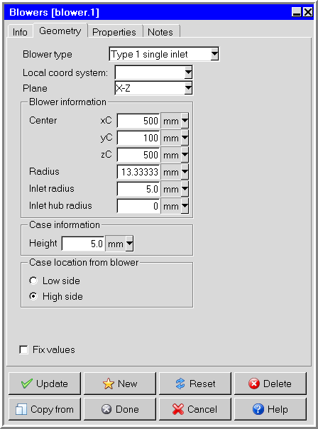
For an impeller, select either Type 1 single inlet or Type 1 dual inlet in the Blower type drop-down list. For a dual-inlet impeller, the inlet openings will be aligned on the top and bottom of the impeller and will have the same inlet and hub radii.
Specify the plane in which the impeller lies (Y-Z, X-Z, or X-Y) in the Plane drop-down list.
Under Blower information, enter values for the Center point of the base side (xC, yC, zC), the Radius, the air Inlet radius, and (optionally) the Inlet hub radius.
Under Case information, enter a value for the Height of the impeller.
Under Case location from blower, specify the direction in which the impeller should extend from its base side by selecting Low side for the negative coordinate direction or High side for the positive coordinate direction.
Centrifugal blowers:
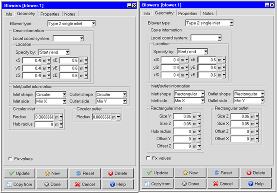
For a centrifugal blower, select either Type 2 single inlet or Type 2 dual inlet in the Blower type drop-down list. For a dual-inlet centrifugal blower, the inlet openings will be aligned on opposite sides of the device and will have the same size, shape, and hub radii. See Figure 22.6: Centrifugal Blowers Geometry Panel for an example of inputs used for a centrifugal blower.
Under Case information and Location, select Start/end in the Specify by drop-down list and enter values for the start coordinates (xS, yS, zS) and end coordinates (xE, yE, zE, as appropriate) of the base, or select Start/length and enter values for the start coordinates (xS, yS, zS).
Specify the shape of the inlet opening(s) by selecting Circular or Rectangular in the Inlet shape drop-down list.
Specify the shape of the outlet opening by selecting Circular or Rectangular in the Outlet shape drop-down list.
Specify the Inlet side in the drop-down list. For a single-inlet blower, you can select any of the six sides of the case (Min X, Min Y, Min Z, Max X, Max Y, Max Z). For a dual-inlet blower, you can select any pair of sides that face the same coordinate direction (Min/max X, Min/max Y, Min/max Z).
Specify the Outlet side in the drop-down list. Your options will be limited to those sides that are perpendicular to the side(s) containing the inlet opening(s). For example, if the inlet opening was located on the Min X side of the case, you could specify the outlet opening to be on the Min Y, Max Y, Min Z, or Max Z sides of the case.
Specify the geometry of the inlet opening(s).
Circular inlets: Under Circular inlet, specify a value for the Radius and, optionally, the Hub radius.
Rectangular inlets: Under Rectangular inlet, specify values for the length and width of the opening (that is, Size X, Size Y, or Size Z depending on the direction of the opening) and, optionally, the Hub radius. Also, specify the offset distances from the center of the face (that is, Offset X, Offset Y, or Offset Z).
Specify the geometry of the outlet opening.
Circular outlets: Under Circular outlet, specify a value for the Radius.
Rectangular outlets: Under Rectangular outlet, specify values for the length and width of the opening (that is, Size X, Size Y, or Size Z depending on the direction of the opening) and the offset distances from the center of the face (that is, Offset X, Offset Y, or Offset Z).
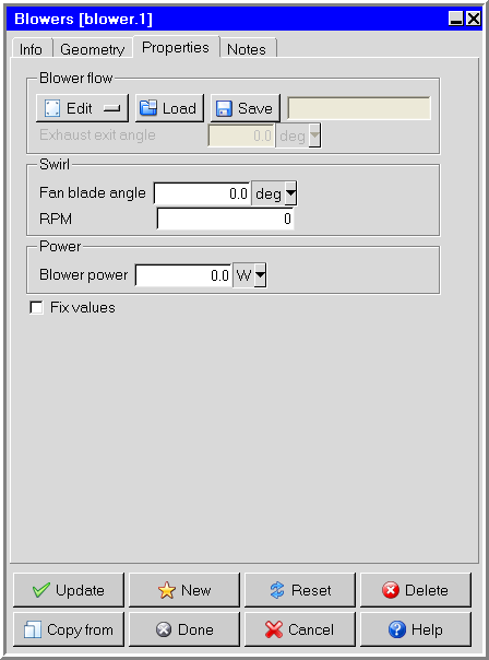
In the Properties tab, specify the internal properties of the blower.
Under Blower flow, define the characteristic curve for the blower as a curve consisting of piecewise-continuous line segments. Ansys Icepak allows you to describe the curve either by positioning a series of points on a graph using the Blower curve graphics display and control window (see Using the Fan curve Window to Specify the Curve for a Characteristic Curve Fan Type for a description of the similar Fan curve window), or by specifying a list of blower static pressure/volume flow rate coordinate pairs using the Curve specification panel (see Using the Curve specification Panel to Specify the Curve for a Characteristic Curve Fan Type). These options are available under Edit.
To load a previously defined curve, click Load. This will open the Load curve file selection dialog box. Select the file containing the curve data and click Accept. See File Selection Dialog Boxes for details on selecting a file.
To save a curve, click . This will open the Save curve dialog box, in which you can specify the filename and directory to which the curve data is to be saved.
Note: The box to the right of Save will be empty if you have not defined a curve for the blower. This box will contain the first volume flow value if you have defined a curve.
(For type 2 blowers only) Specify the Exhaust exit angle for centrifugal blowers.
(For impellers only) Under Swirl, specify the Fan blade angle and the RPM.
Note: For a blowers rotating clockwise, make sure to specify the RPM as a negative value. If a blower is rotating counter-clockwise, make sure to specify the RPM as a positive value. For example, using the right-hand rule, a blower in the x-y plane that is rotating counter-clockwise will have its normal pointing in the positive z direction. If the same blower was rotating clockwise, the normal would point in the negative z direction.
Note: If the impeller Fan blade angle is unknown and specified as 0, a default value of 1 radian is used.
Under Power, specify the Blower power. This value is the amount of energy, in the form of a volumetric heat source, that is absorbed by the blower from the motor. The blower power is an indirect specification of the blower’s efficiency, similar to the hub power for a fan.