


To set meshing options for your model, select the Meshing item under the Defaults node in the Preferences panel (Figure 8.17: The Meshing Section of the Preferences Panel).
![]() Defaults
Defaults 
 Meshing
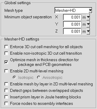
Mesh type is used to specify the type of mesh to be used in your Ansys Icepak project. By default, Ansys Icepak uses the Mesher-HD option, which denotes an unstructured mesh. The other mesh types you can choose from are Hexa unstructured and Hexa cartesian.
Enable non-isotropic 3D cut cell transition is used to determine how the 3D cut cell mesh generation method subdivides cells near objects. By default, 3D cut cell uses isotropic subdivision which split a hexahedron cell into 8 children hexahedra cells. If Enable non-isotropic 3D cut cell transition is enabled, the subdivision is done anisotropically. The nonisotropic subdivision will create N number of mixed cell types (hexahedra, tetrahedra, prisms and pyramids). The non-isotropic subdivision will lead to a faster meshing time but will contain more cells than an isotropic subdivided mesh.
Minimum object separation is used to specify the minimum distance separating objects in your model in the x, y, and z coordinate directions. This distance may be expressed in any valid number format (for example, 0.001, 1e-3, 0.1e-2). This specification is used by Ansys Icepak whenever the distance between two objects is less than this value, but greater than the model’s zero tolerance.
Enforce 3D cut cell meshing for all objects is a meshing technique used to body-fit the mesh to certain complicated shapes like CAD, ellipsoids, elliptical cylinders and intersecting cylinders. It is used when Allow multi-level meshing option in the Mesh control panel is switched on. When the Enforce 3D cut cell meshing for all objects is switched on, all objects irrespective of their shapes will be meshed using this cut cell technique.
Optimize mesh counts in thickness direction for package and PCB geometries are applicable to the hex-dominant mesher (Mesher-HD) only. When this option is on, the mesher will try to put single elements in the thickness direction of each of the objects and/or gaps like solderballs, die, and so on that are enclosed by a package or pcb except for trace heating layers (where more than one element may be desired in the thickness direction).
Enable 2D multi-level meshing is used with the hex-dominant mesher only and starts with coarse background meshes and then refines the mesh to resolve fine-level features. This is a meshing technique for all shapes except for CAD objects, non-uniform polygonal objects and non-single axis aligned objects. 2D multi-level meshing can be activated when this option is switched on along with the Allow multi-level meshing option in the main Mesh control panel. Its advantage over 3D cut cell meshing is that it can be used on objects with smaller thicknesses such as trace heating layers. There is no stairsteps meshing involved in this option.
In general Isotropic refinement enables you to refine the mesh regardless of the geometry. This option yields higher cell count as compared to anisotropic refinement but quality of cells may be better, as aspect ratio is maintained in 2D.
By default Anisotropic refinement enables you to refine the mesh in adapting to the geometry. This option yields lower cell count but quality of cells may be affected depending on the geometry.
Enable mesh by layer in 2D multi-layer meshing is used to create 2D multi-level mesh separately according to different geometry layers.
Detect gaps between overlapped objects is used to identify gaps between objects that overlap (such as an object within another object) when enforcing minimum elements in gap mesh parameter. To include gap detection between overlapping objects, enable Detect gaps between overlapped objects before meshing.
Insert prism layer in Joule heating blocks is used to automatically inflate a prism cell layer mesh from the inward facing boundary of the Joule heating blocks.
Force nodes to assembly interfaces is used to move mesh nodes onto assembly boundaries.