


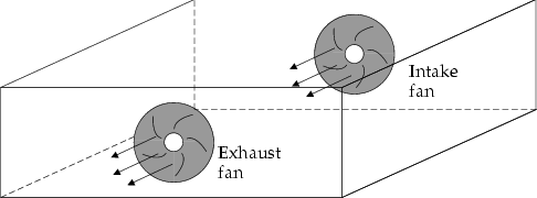
Figure 21.1: Intake and Exhaust Fans shows two fans on the cabinet boundary; one defined as an intake fan and the other defined as an exhaust fan. The intake fan draws fluid into the cabinet. By default, Ansys Icepak assumes that the intake fluid is at ambient temperature. The exhaust fan expels fluid from the cabinet in a direction determined by the local flow conditions. By default, the fluid exits the cabinet at the temperature computed for the fluid within the cabinet at the intake side of the fan.
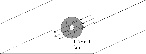
Characteristic curve fans can be defined as exhaust, intake, or internal. Internal fans are located entirely within the cabinet (see Figure 21.2: Internal Fan Placement) and are surrounded by fluid on all sides. The direction of flow through an internal fan can be specified as positive or negative, relative to the coordinate axis normal to the plane of the fan.
To configure a fan in the model, you must specify its geometry (including location and dimensions), its type, the flow rate associated with the fan, and the swirl. For a transient simulation, you must also specify parameters related to the strength of the fan for a characteristic curve fan. You can also specify the species concentrations and turbulence parameters at the fan.