Post-process the solution by creating object faces and a summary report.
Click the object face button (
 ) to open the Object face
panel.
) to open the Object face
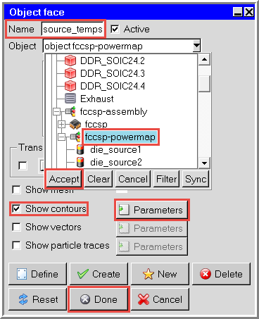
panel.From the Object drop-down select the fccsp-powermap assembly and click Accept.
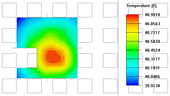
Select Show contours and click Parameters to open the Object face contours panel.
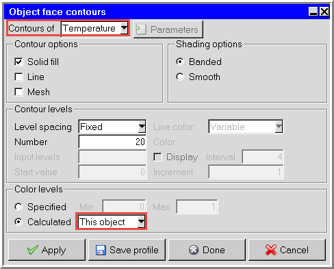
In the Object face contours panel, ensure Temperature is selected, and select This object.
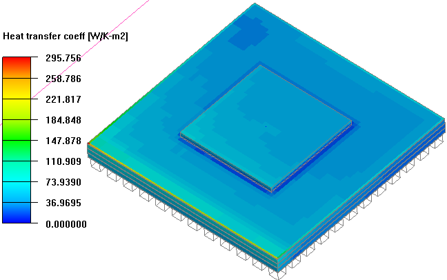
Click Done in the Object face contours panel and then Done again in the Object face panel to display the temperature contours.
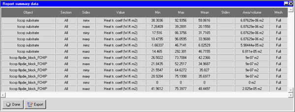
To determine the heat transfer coefficient range on the package object, create a summary report by selecting Report > Summary report to open the Define summary report panel.
Define the report entries as shown in the image below, selecting the substrate an die objects under the fccsp package and setting Heat tr coefficient as the Value.
Click Write to display the summary report.
Note the minimum and maximum values in the report (0 and 295.756, respectively). We will input these values when creating an object face to display the heat transfer coefficient on the substrate and die blocks. Click Done to close the summary report, and click Close to close the Define summary report panel.
Note: Negative values correspond to heat entering the object at that surface.
From the Post menu, select Object face (facet) to open the Object face (facet) panel.
Enter a Name of fccsp-htc.
In the Object drop-down list, expand the fccsp package and select the substrate and three die objects.
In the Contours of drop-down list, select Heat transfer coefficent.
Under Color levels, select Specified and enter 295.756 for the Max value.
Click Display to display the object face in the Graphics window.
Close the Object face (facet) panel.
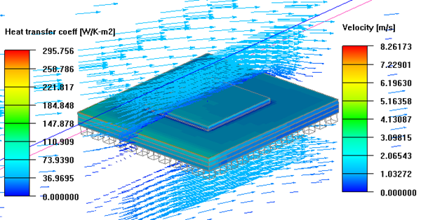
If desired, create additional post-processing objects, such as a cut plane displaying velocity vectors as displayed in the following image.

_panel.png)