Before generating the mesh, define non-conformal mesh settings to avoid mesh bleeding and minimize cell count as well as per-object mesh settings to ensure a good grid transition between the assembly non-conformal mesh and the background mesh.
Create an assembly that includes the fccsp package and the powermap assembly. Press and hold the Ctrl key to select the fccsp-powermap assembly and the fccsp package object. Right-click and select Create Assembly. Change the name of the newly created assembly to fccsp-assembly.
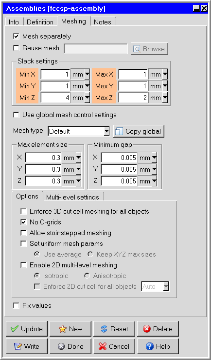
Double-click the fccsp-assembly to open the assemblies panel. On the Meshing tab, select Mesh separately and ensure the settings match those in the following image.
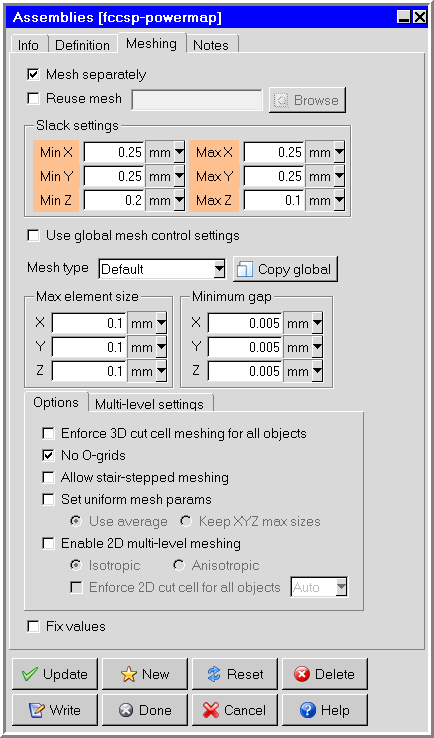
Double-click the fccsp-powermap assembly to open the assemblies panel. On the Meshing tab, select Mesh separately and ensure the settings match those in the following image.
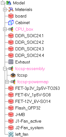
Ensure the model tree appears as it does in the following image.
Click the Generate mesh button (
 ) to open the Mesh control panel.
On the Local tab, click Edit params to open the Per-object meshing parameters panel.
Select the fccsp-assembly, and select the Outside X count and Outside Y count check boxes,
Enter 10 for the requested values, and click Done.
On the Mesh control panel, click Generate to generate the mesh.
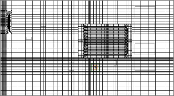
After the mesh is generated, click the Display tab, select Display mesh.
Under Display attributes, select Cut plane.
Note: It is recommended that you perform a grid sensitivity study when working with your own models. For the purposes of this tutorial, we will assume the mesh is acceptable.