At this stage, we will apply non-conformal mesh settings.
In the Model manager, right-click on the Laird_HT4_12_F2_3030.1 assembly and select Create assembly.
Double-click on the new assembly and enter a Name of TECs on the Info tab.
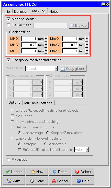
On the Meshing tab, enter the Slack settings as shown in Figure 36.17: TECs Assembly - Meshing Tab.
Leave the other default mesh settings. Click Update and Done.
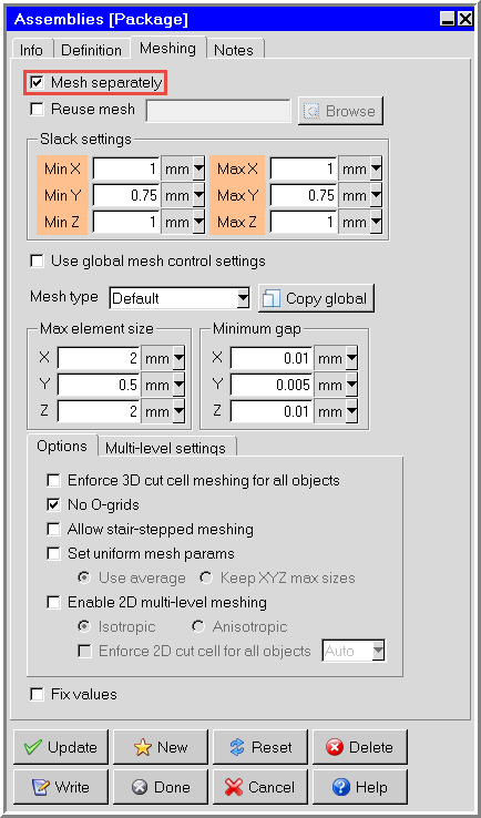
In the Model manager, double-click the Package assembly and go to the Meshing tab.
Select Mesh separately and view the Slack settings.
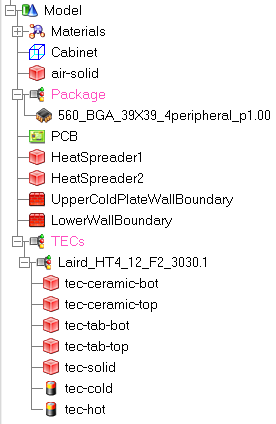
Click Update and Done to close the Assemblies panel. The Model manager should appear as shown in Figure 36.19: Model Manager.
Note: Before continuing to generate a mesh, ensure the Model manager appears as it does in the image above. If an object is included in an assembly erroneously, move it outside the assembly before continuing.
.