On the SIwave Simulation tab, click Icepak.
In the Icepak Simulation Setup dialox box, specify a new Setup Name for the simulation, such as
Icepak Sim 1 - Convection.For DC Sim Results, note that the initial DC IR solution is automatically selected.
For DC Power Convergence, retain the default and ensure Repeat simulations until DC convergence is enabled.
Under Thermal Simulation Type, select Convection (Components optional).
Retain the settings for Meshing Detail and Board Outline Fidelity.
Select Use Classic Icepak.
If High Performance Computing licensing is available, increase the Number of cores to use to 4.
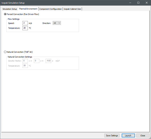
On the Thermal Environment tab, retain the settings for Forced Convection.
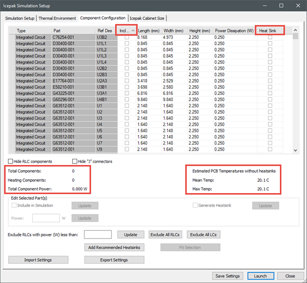
On the Component Configuration tab, click the Heat Sink column header to deselect all check boxes in the column. Also click the Include column header twice to deselect all check boxes in column to match conduction-only settings.
Note: Component Type, Part, and Reference Designator information is displayed in the table. Length and Width should be accurate. Verify the Height and Power Dissipation.
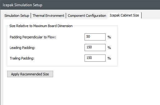
On the Icepak Cabinet Size tab, enter the padding settings under Size Relative to Board Dimension as displayed in the image below.
Click Save Settings.
Click Launch to start the Icepak simulation. The simulation progress is displayed in the Process Monitor.
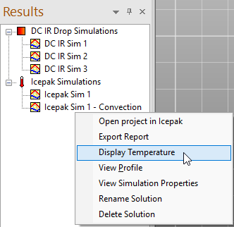
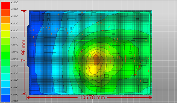
When the simulation loop is complete (after DC IR Sim 2), right-click on the Icepak simulation in the Results pane (Icepak Sim 1 - Convection) and select Display Temperature to show the temperature contours.
Note: Temperature distribution is slightly different due to true fluid flow calculations rather than an estimated boundary condition (as in conduction-only modeling).