These task panels are associated with multiple other task panels, or accessed through Common Ribbon Elements.
The Part On/Off task panel enables you to turn parts of the project on and off by selecting them from a list or in the graphics window. You can also perform basic logical operations to modify the part selection. Open this task panel by selecting Part On/Off in the ribbon.
The Part Transform task panel enables you to pick a coordinate system and parts of the project, then apply a distance-based translation or degree-based rotation. Access this task panel by choosing Transform from the ribbon.
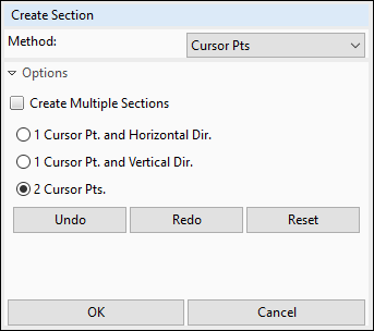
The Create Section task panel enables you to define a cut line through the project geometry by drawing it in the graphics window and it to display a cross-section view of the blank. Access this task panel by choosing Section Cut from the ribbon.

This tool is useful during both postprocessing analysis and while defining operations. While on the Operations tab, use sections to preview tool movement. The shapes of tooling may block important surface interactions from view. Define a section to reveal the profiles of these interactions. (The position and shape of the blank will not change during the animation.) On the Analysis tab, create sections to view simulation data along particular cross-sections of the part.
The first time you click in a project, the Create Section task panel opens. Choose a Method from the drop-down menu, and options for that method. Then, use the method to define the cut line or lines, and click .

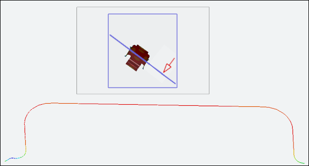
While any section cuts are active, a subwindow displays the fulll model as a thumbnail. A line on the thumbnail shows the location of the section cut. An arrow on the thumbnail shows the direction from which you are viewing the section cut. Move the section cut through the model using the left and right arrow keys on your keyboard. Increase and decrease the movement increment using the up and down arrow keys on your keyboard.
Move the thumbnail subwindow by clicking it and dragging the subwindow to a new location. Resize the subwindow by clicking and dragging its border. You can hide the thumbnail by choosing from the drop-down menu below the button on the ribbon.
Click again to remove the section cuts from the graphics window and return to the standard view.
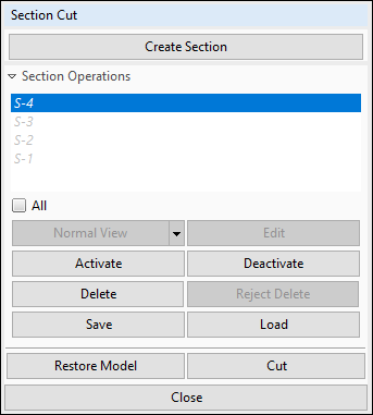
The Section Cut task panel enables you to manipulate Section Operations that you have defined. Access this task panel by clicking the triangle below Section Cut in the ribbon, and choosing .

If you have not yet created any Section Operations, click to open the Create Section Task Panel. When you return to the task panel, any sections operations you created are listed in the list. Active sections are displayed with an asterisk ("*") after their names. Click a section's name to select it, or check the box next to All to select all sections.
To activate a section cut, select it in the list and click . The cut plane of the section is displayed on the model. To show active sections, click . You can activate and deactivate sections while cuts are diaplayed. To display the full geometry, click .
To align the normal of the selected cut plane with the view, click . To see the reverse of that view, click the triangle on the button and choose from the drop-down menu.
To modify the definition of the selected section, click to open the Edit Section task panel. Choose a Method from the drop-down menu, and options for that method. Then, use the method to modify the cut line, and click .
You can also remove the selected section from the project by clicking . If you made a mistake, click to restore the section.
Save all selected section operations by clicking and using the dialog box to save the Section Cut Data File (a .xml file) in a memorable location. It is best to use a central location, and not a specific project directory. You can then open the Section Cut task panel in another project and click the button to copy the section operations from one project to the other.
When you are finished with the task panel, click to remove it. Any active sections displayed in the graphics window will stay active until you click in the ribbon or return to the Section Cut task panel and restore the model.
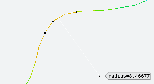
The Measure task panel enables you to measure distance, radius, and angle on the project geometry by picking nodes or points in the graphics window. Access this task panel by choosing Measure from the ribbon.
Choose the type of measurement from the menu attached to the button in the ribbon, or from the Measure Item menu in the task panel. Then, pick the required number of nodes or points by clicking in the graphics window or by entering coordinates (for points) and clicking . You may find it easier to pick nodes or points by selecting the Snap check box to snap cursor movement to locations on the blank. When you have picked the required number of locations, the chosen measurement is displayed in the graphics window.

You can use this tool together with the tool to measure distances and radii in the middle of the model where it can be difficult to pick points in a single plane.
Select more points to display new measurements. Click to remove all measurements from the graphics window.


