


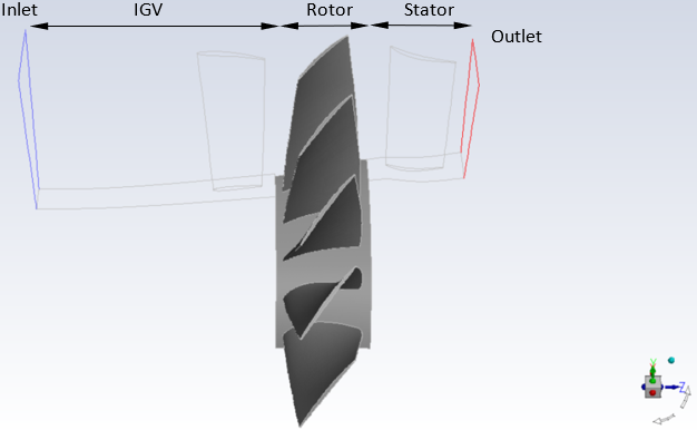
In the most common scenario, the blade of interest for calculating the aerodynamic damping value is situated between two rows or at least adjacent to another blade row. For example, the figure below shows a 1.5-stage axial compressor with vibrating rotor blades between the IGV and stator blade rows. A requirement for using the energy method is the inlet flow is pitchwise averaged so the typical workflow is to extract the profiles from a multi-row analysis and impose the pitchwise value on the transient aerodynamic damping analysis. To avoid this two-step workflow, the aerodynamic damping analysis can be performed on the rotor while using the Mixing-plane interface between the IGV and the rotor and another mixing-plane interface between the rotor and the stator. This modeling configuration can also help mitigate boundary reflections since the inlet and outlet boundaries are now placed away from the rotor.
With beta features enabled, you can model such a multi-stage turbomachinery case with a vibrating blade flutter row using the ICM method in Fluent. The procedure to set up the multi-stage turbomachinery case using the ICM is similar to the single-blade row ICM case, apart from specifying the vibrating blade flutter row. In the multistage turbomachinery case with the blade flutter row, you must specify the blade flutter row before assigning the periodic displacement group to the vibrating blades using the text command:
define/turbo-model/blade-flutter-row/