Two models are available in Ansys Fluent for the treatment of porous media:
The (full) porous media model
The ‘porous jump’ condition
The porous media model is applied in a cell zone. Several input parameters can be specified to determine the pressure loss in the flow. The ‘porous jump’ condition is a 1D simplification of the porous media model and is applied to a face zone.
In the porous medium the standard conservation equations for turbulence quantities are solved by default. The turbulence inside the porous medium is treated as though the solid medium has no effect on the turbulence production and dissipation rates. A detailed description of these models can be found in the Ansys Fluent User’s Guide.
An enhancement to the ‘porous jump’ condition is now available as a beta feature, allowing you to enable a wall treatment at the fluid side of the interface for both laminar and turbulent flows. When you assume, for example, fluid flow over a porous medium, then the porous medium has an effect on the fluid similar to a wall at the interface depending on its porosity. This beta option has been introduced to include the effects of the porous material on the fluid side of such an interface. An Example shows the combination of the beta ‘porous jump’ option with a porous media zone.
The near-wall treatment on the fluid side of a fluid/porous media interface involves the following:
The wall shear stress is introduced at the interface for the momentum equation.
In the case of turbulent flows, in the transport equation for the specific dissipation rate
 or dissipation rate
  , wall values are prescribed.
Furthermore, the diffusion term is set to zero at the interface.
For turbulent flows, the near-wall distance is updated to obtain a proper wall treatment. The near-wall treatment that is used at the interface behaves identically to that of a solid wall, also with respect to y+.
Near-wall treatment for the porous media interface is available after enabling beta feature access, as described in Introduction.
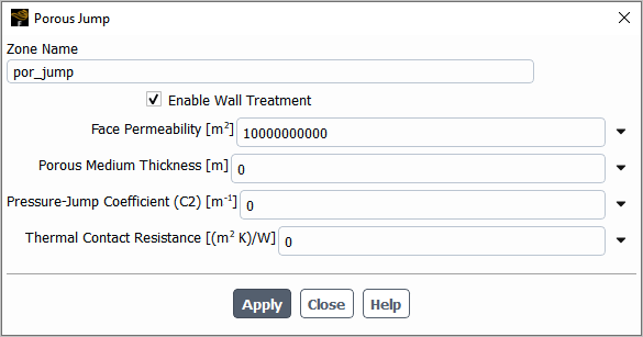
The Enable Wall Treatment option in the Porous Jump dialog box (see Figure 10.9: The Porous Jump Dialog Box) is used to enable or disable a turbulent near-wall treatment on the fluid side of a ‘porous jump’ interface. In the Viscous Model dialog box, different near-wall treatments can be selected, depending on the turbulence model. The selected treatment is then applied both for solid walls and at the fluid side of the interface.
The Enable Wall Treatment option can be used together with either laminar or the following turbulence models: k-epsilon and k-omega turbulence models, SST and Transition SST, Reynolds Stress models, Detached Eddy Simulation (DES) and Scale-Adaptive Simulation (SAS).
As outlined in the introduction, the purpose of the Enable Wall
Treatment option is to include the effects of the porous material on the flow, for
example, at an interface between a fluid and a porous medium. Figure 10.10: Setup of Two Channel Flows Separated by Wall / Porous Jump Interface; Color Denotes
Contours of the Streamwise Velocity Component. shows the setup of two channel flows, which are separated by a wall in the first part and by
a ‘porous jump’ interface in the larger second part. The Reynolds number based on
the centerline velocity and channel half height in each channel is  .
.
The lower zone in the second part is defined as a cell zone where the porous media model
has been activated. A viscous loss term has been specified with a small viscous resistance of
 in the streamwise direction. The interface between the lower porous media zone
and the upper pure fluid zone has been defined as ‘porous jump’ with a medium
thickness of zero. Therefore, no pressure jump occurs across the interface. It is only used to
enable the wall treatment at the fluid side of the interface. Two simulations have been
performed with and without the wall treatment at the interface in order to investigate the
influence.
in the streamwise direction. The interface between the lower porous media zone
and the upper pure fluid zone has been defined as ‘porous jump’ with a medium
thickness of zero. Therefore, no pressure jump occurs across the interface. It is only used to
enable the wall treatment at the fluid side of the interface. Two simulations have been
performed with and without the wall treatment at the interface in order to investigate the
influence.
Inlet boundary condition profiles are prescribed for the velocity and the turbulence quantities which have been obtained from a 1D periodic channel flow. The outlet is specified as ‘pressure outlet’. The grid is refined both to the walls (y+ ~ 2) and to the interface. The SST turbulence model has been used for both simulations.
Figure 10.10: Setup of Two Channel Flows Separated by Wall / Porous Jump Interface; Color Denotes Contours of the Streamwise Velocity Component.
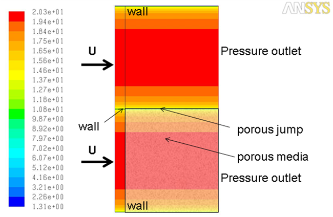
Figure 10.11: Profiles of the Streamwise Velocity Component Near the Outlet at Position x = 0.9 m Without (top) and With (bottom) Near-Wall Treatment at the Interface. Red Denotes the Pure Fluid Side, Black Represents the Side of the Porous Media shows profiles of the streamwise velocity component at position x = 0.9 m near the outlet without (top) and with (bottom) near-wall treatment at the interface. The profiles in the pure fluid zone are colored in red. The profiles in the zone where the porous media model is activated are colored in black.
The inclusion of the wall shear stress in the momentum equation has reduced the streamwise velocity at the interface on the fluid side. In the figure's cell center, values have been plotted to allow a direct comparison with the effect caused by the walls. The effect of the new treatment at the interface is similar to the influence of the upper wall.
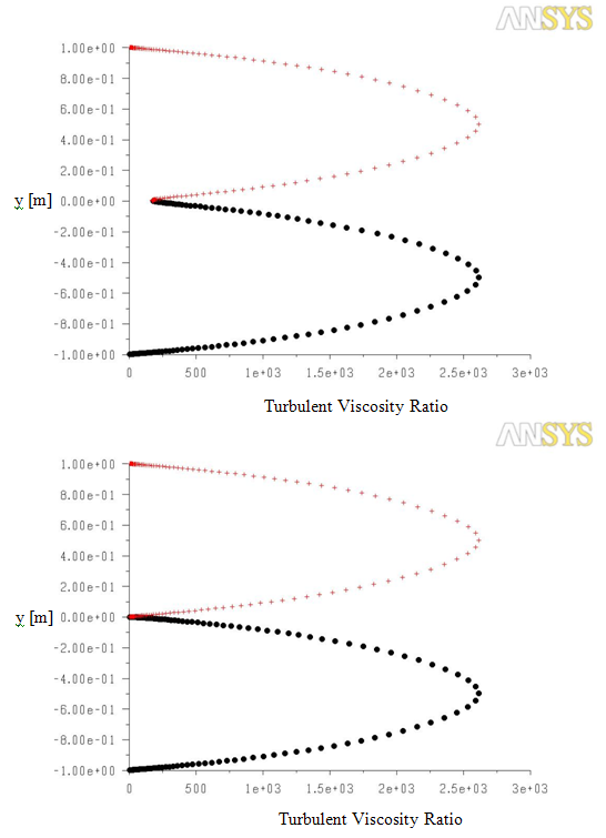
The profiles of the turbulent viscosity ratio are shown in Figure 10.12: Profiles of the Turbulent Viscosity Ratio Near the Outlet at Position x=0.9m Without
(top) and With (bottom) Near-Wall Treatment at the Interface. Red Denotes the Pure Fluid Side,
Black Represents the Side of the Porous Media. In this simulation, a fine grid has been used that allows you to
resolve the viscous sublayer. The eddy viscosity ratio is nearly zero close to the walls. The
interface shows the same effect due to the additional source term in the  -equation when the near-wall treatment has been enabled and reduces the
turbulent viscosity ratio.
-equation when the near-wall treatment has been enabled and reduces the
turbulent viscosity ratio.
Figure 10.11: Profiles of the Streamwise Velocity Component Near the Outlet at Position x = 0.9 m Without (top) and With (bottom) Near-Wall Treatment at the Interface. Red Denotes the Pure Fluid Side, Black Represents the Side of the Porous Media
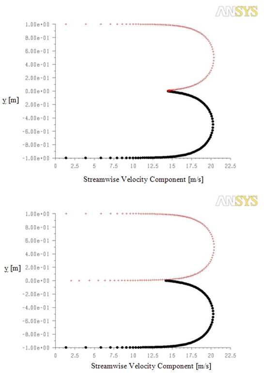
Figure 10.12: Profiles of the Turbulent Viscosity Ratio Near the Outlet at Position x=0.9m Without (top) and With (bottom) Near-Wall Treatment at the Interface. Red Denotes the Pure Fluid Side, Black Represents the Side of the Porous Media