Traditionally, when you setup your case by defining boundary conditions and so on, it may seem as though you are specifying them on your model, but they are actually being defined on the loaded mesh. Since it is important to confirm your results are not mesh dependent. Thus, with the old approach you are forced to re-setup the same problem multiple times.
Fluent 2024 R2 uses a topology model that allows you to define physics settings on your model. Thus, with careful naming, you can swap out meshes for a case without needing to fully re-define your setup. With this new approach, the physics definitions are separate from the geometry, giving the option to setup the physics independently of the geometry and mesh.
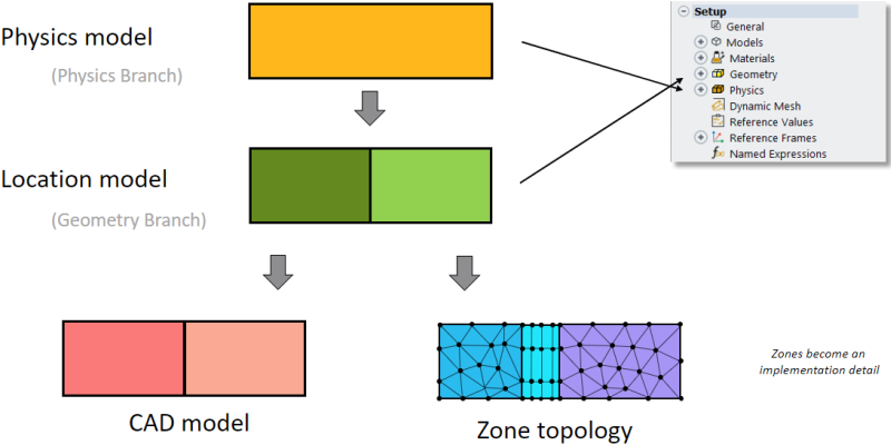
Model Topology is the representation of your model. It is the "location". Physics are the settings describing the problem you are trying to solve. You will connect your physics definitions to the locations on your model topology where they are relevant.
There are a number of benefits to using the UTL approach in Fluent:
The setup is entirely based on labels, which are equivalent to names and named selections. Thus, scripting is simplified because you only have to know the labels to properly define the problem—no need to know ids.
Platform and core count independent setup.
Labels can be grouped together, allowing for a simplified setup on a few groups rather than many zones.
The setup is decoupled from a specific topological representation.
You can setup the physics prior to meshing.
Geometry and mesh can change as long as the labels remain the same.
Easy transfer of setups between similar problems, for example, using templates.
The topology information is persistent and shared using the Common Fluids File format (CFF).
Allows for the consistent exchange of setup based on labels for all products in the Fluids Business Unit (FBU)
EnSight and CFD-Post allow for consistent comparison and postprocessing of results, using CFF.
Model-specific zone creation happens behind the scenes (for example, zones are created for certain porous models).
The Outline View tree is where the differences between the traditional, zone-based case specification, and the UTL approach are most apparent. The branches are as follows:
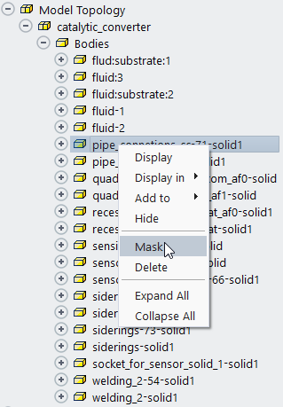
Model Topology—The Model Topology branch lists all of the bodies, volumes, boundaries, and groups associated with the model geometry.
Entities under this branch can be grouped to simplify setup on the physics-side. For example, if you have a set of boundaries or zones requiring identical setups, you can group them together for assigning physics.
You can also mask areas of the geometry that you do not want included in the simulation. Right-click the selected bodies and select Mask to hide them from the solver. That is, masked bodies do not need a corresponding physics definition.
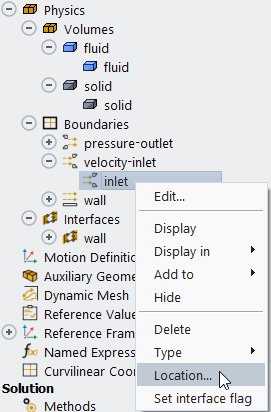
Physics—The physics branch lists all of the physics volumes, boundaries, and interfaces defined in this case. When these physics definitions are fully specified, they also reference the locations where they are applied. The available locations are based on the items listed in the Model Topology branch.
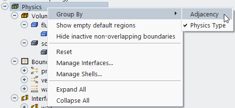
You can control how physics volumes and boundaries are grouped by selecting either Physics Type (default) or Adjacency from the Group By context menu option, accessed via right-click of the Physics branch.
Right-click a physics definition and select Location... to open the Edit Physics Location dialog box. Here you specify the geometrical body, bodies, or group where this physics condition will be applied.
Interfaces—A physics interface is a unified generalized mesh interface that includes setup of the (sided) physics. This means it handles conformal and non-conformal connections between regions. The setup of these interfaces is independent of the mesh connectivity. Periodic interfaces are also included.
Icons are used to visually identify the interface type in the tree:
 —indicates a solid-fluid interface.
 —indicates a solid-solid interface.
 —indicates a fluid-fluid interface.