


In Workbench, you can create connections between multiple systems that enable the systems to access the same data. This is useful, for instance, when you want to compare the results from multiple Fluent-based systems in the same Ansys CFD-Post session. In this case, you would connect the various Solution cells to one Results cell (either in one of your Fluent-based systems or in a separate Results system). When you double-click that Results cell, the results from all connected systems will be loaded into Ansys CFD-Post at the same time.
Another example would be where you want to load multiple meshes created in the Ansys Meshing application to your Fluent-based system. See Connecting Multiple Upstream Meshes to a Setup Cell of a Fluent-Based System for further information on such connections.
Workbench supports two different types of connections:
Shared data connections
Used when the inputs and outputs of the two connected cells are identical
Can only be created between two cells of the same type
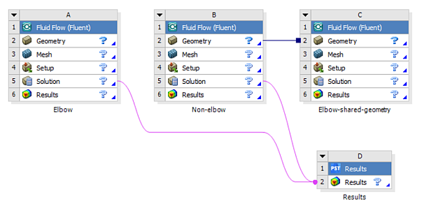
A shared data connection is represented in the Project Schematic by a line with a square on its right (target) side
 (see Figure 2.4: Connected Systems Within Workbench).
Transfer data connections
Used when the output of one cell is used as the input to the connected cell
Usually created between two cells of different types. One exception is that a transfer data connection can be used between the Solution cells of two Fluent-based systems when you want to use the current data from one system as the initial data for the other system.
A transfer data connection is represented in the Project Schematic by a line with a circle on its right (target) side
 (see Figure 2.4: Connected Systems Within Workbench).
There are four ways to create connected systems in Workbench.
Click a cell in one system, then drag and drop it onto a compatible cell in another system.
Click a system in the Toolbox, then drag and drop it onto a compatible system in the Project Schematic.
Create a duplicate system (see Duplicating Fluent-Based Systems).
Right-click a cell and select one of the options under Transfer Data From New... or Transfer Data To New... (these options are not available for all cells). Transferring data from the Solution cell to a new Fluent system's Setup cell transfers the mesh (but not the settings) to the Setup cell.
When you click and hold down the mouse button at a system in the Toolbox, Workbench highlights all of the compatible drop targets in the Project Schematic. As you move the mouse over a drop target, it is highlighted in red and a message appears in the Project Schematic that informs you what the result will be if you drop the system onto that target.
There are usually several compatible drop targets on empty space in the Project Schematic. Dropping the system onto one of these targets will create a stand-alone system in that location.
Similarly, when you highlight a cell and begin to drag it, Workbench highlights all of the compatible drop targets in the Project Schematic. As you move the mouse over a drop target, it is highlighted in red and a message appears in the Project Schematic that informs you what the result will be if you drop the cell onto that target.
For more information about connecting systems, see the Workbench online help, as well as the following sections:
You can connect multiple Mesh cells of Mesh component systems to the Setup Cell of a Fluent-based system. The mesh data, including the mesh input parameters that you may have defined in the Ansys Meshing application, will then be transferred to the Setup cell. When you start Fluent from the Setup cell, Fluent will read the mesh data from the connected Mesh cells in the order in which the connections were created. If your Fluent-based system contains a Mesh cell, Fluent will read this data first.
Note the following limitation with these connections:
If any upstream mesh is modified while the currently open Fluent session is running, then on refresh, Fluent will reload all mesh files.
Important: If you change the zone topology of one of the upstream meshes, Fluent may report a mesh incompatibility. You must then resolve the mesh incompatibility issue in order to proceed with the case setup.
The following example demonstrates the procedure for creating connected systems by dragging a system from the Toolbox and dropping it onto a compatible system in the Project Schematic. (See Figure 2.5: Applying the Mesh Settings to a New Fluent-Based Component System by Dragging and Dropping Systems)
Figure 2.5: Applying the Mesh Settings to a New Fluent-Based Component System by Dragging and Dropping Systems
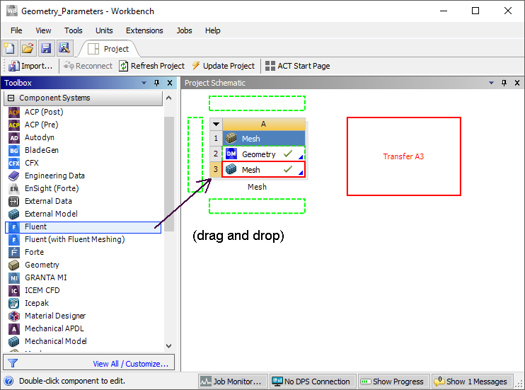
Starting from a project with an up-to-date Mesh component system, select the Fluent-based component system from the Toolbox; the compatible drop targets are highlighted in green.
Drag the system over the Project Schematic and pause over the Mesh cell of the Mesh component system; the Mesh cell target is highlighted in red and a message informs you that selecting that target will transfer the data from cell
A3to the new system.Drop the system on the drop target and a transfer data connection is created between the Mesh cell
A3and the Setup cellB1.Note that Mesh cell
A3becomes Update Required, this is because the input data for the new system has not yet been generated by the Ansys Meshing application.Important: If you try to open Fluent before the Mesh cell is updated, a warning message is displayed informing you that you must update the Mesh cell before you can start Fluent, since the mesh file required for Fluent does not yet exist.
Right-click Mesh cell
A3and select Update.Double-click Setup cell
B1; Fluent launches and loads the mesh from cellA3.
In the previous example, a transfer data connection was created. Shared data connections can also be creating by dragging a system from the Toolbox and dropping it onto a compatible system in the Project Schematic. The type of connection that Workbench creates depends on which drop target you select. The red preview messages in the Project Schematic inform you of the type of connection(s) that will result from your action.
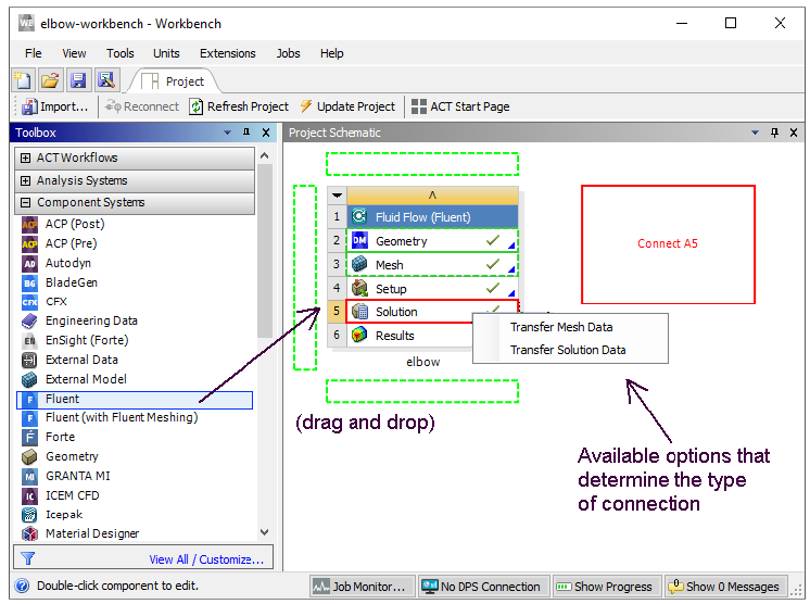
When a Fluent-based component system is dragged from the Toolbox onto the Solution cell of an existing Fluent-based analysis system, you are presented with two choices: Transfer Solution Data or Transfer Mesh Data. The connection that is made between the two systems is based on the option selected.
Figure 2.6: Transferring Solution Data or Mesh Data to a New Fluent-Based Component System by Dragging and Dropping Systems
Important: The mesh from the case file associated with the Solution cell of a Fluent-based analysis system or component system can be transferred to the Setup cell of a Fluent-based component system only and not the Setup cell of a Fluent-based analysis system.
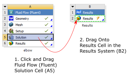
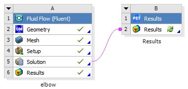
The following figures demonstrate the procedure for creating a transfer data connection by dragging a Solution cell from a Fluent-based system and dropping it onto a compatible cell in another system:
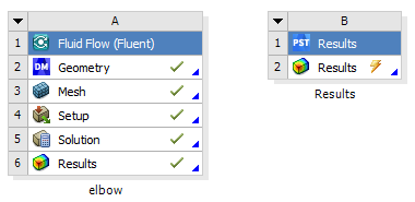
The following table lists the compatible drop targets for the Solution cell from a Fluent-based system:
Table 2.1: Compatible Drop Targets for the Solution cell of a Fluent-Based System
| Analysis or Component System | Cell(s) |
|---|---|
|
Fluent |
Setup Solution |
|
Fluid Flow (Fluent) |
Solution Results |
|
CFX Fluid Flow (CFX) Vista TF Results |
Results |
|
Static Structural (ABAQUS) Static Structural (Samcef) Shape Optimization (ANSYS) Static Structural Steady-State Thermal Transient Structural Thermal-Electric Transient Thermal |
Setup |