


To access and use the Fluent meshing workflows in Workbench, perform the following:
Open the Workbench environment.
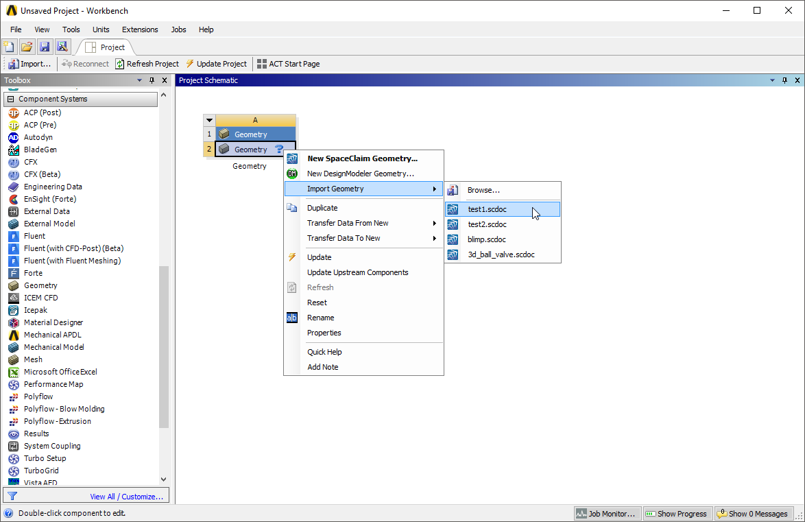
Add a Geometry component system to your Workbench project, and import a CAD geometry file into the Geometry cell.
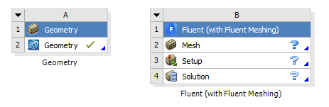
Add a Fluent (with Fluent Meshing) component system to your project.
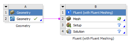
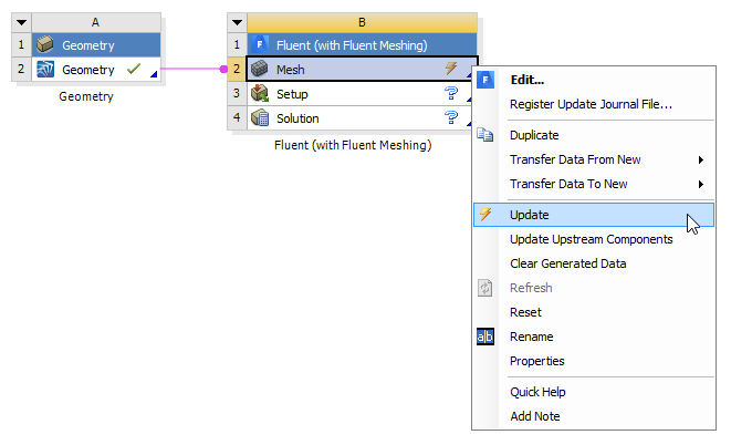
Connect the Geometry cell of the Geometry component system to the Mesh cell of the Fluent (with Fluent Meshing) component system.
Select the Mesh cell and view it's properties.
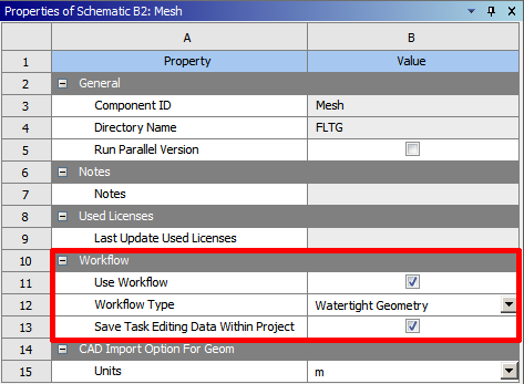
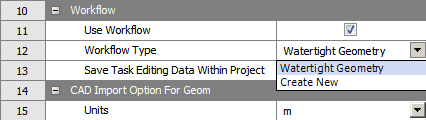
Note the Use Workflow check box in the properties of the Mesh cell. By default, the Use Workflow check box is enabled, and you are able to select a workflow from the Workflow Type field. When the check box is disabled, you are still able to set CAD faceting and other options within the properties of the cell.
The Save Task Editing Data Within Project option (enabled by default) allows you to save relevant task-related data files (such as mesh information and task state) directly in your Workbench project, making it easier to use the workflow, for example, when reverting and editing tasks. This property is available for standalone Fluent (with Fluent Meshing) component systems, whether or not there is a connected upstream Geometry system. If this property is enabled, the Saving data for editing tasks workflow preference will use the Write mesh files option. See Setting Preferences for Workflows in the Fluent User's Guide for more information on workflow preferences.
In the Workflow Type field, select the Watertight Geometry option to use that workflow, or select the Create New option to create your own workflow.
Start Fluent in Meshing mode.
Double-click the Mesh cell in the Fluent (with Fluent Meshing) component, and make any appropriate selections in the Fluent Launcher, then proceed to open Fluent in Meshing mode to start working with a workflow.
The Workflow tab is automatically opened in Fluent and the corresponding workflow is initialized with the imported CAD geometry from the Geometry cell from your Workbench project.
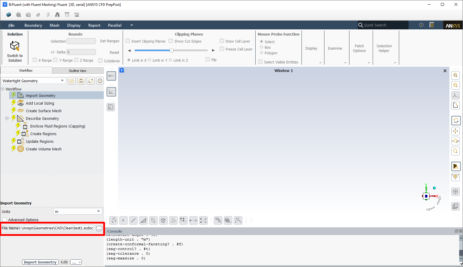
Proceed with setting up the various tasks of the workflow (for example, defining local sizing, capping inlets and outlets, extracting fluid regions, and generating the volume mesh).
Once all workflow tasks are completed (and marked as up-to-date), and a volume mesh is generated, the state of the Mesh cell becomes Up-to-Date.
Tasks can be added, removed, or otherwise customized to your needs, and the configuration will be retained when you return to Fluent from your Workbench project. See Getting Started with the Fluent Guided Workflows in the Fluent User's Guide for more information.
When you have completed setting up the workflow, you can return to your Workbench project and update the Mesh cell in the Fluent (with Fluent Meshing) component.
Proceed, as usual, with completing the CFD simulation through the Setup and Solution cells in the Fluent (with Fluent Meshing) component.
This functionality can be especially useful when you have similar geometries that use the same object labels (for example, different, but similar, manifold geometries that each contain three inlets named
in1,in2, andin3and an outlet namedout1). These similar geometries can be imported using a separate Geometry component that is connected to a single Fluent (with Fluent Meshing) component that already has a workflow defined to generate a compatible volume mesh for the same geometric configuration. The geometries can be swapped out, and once the Fluent (with Fluent Meshing) component is updated, the defined workflow will automatically update itself to generate a corresponding volume mesh.