VMFL065
VMFL065
Swirling
Turbulent Flow Inside a Diffuser
Overview
| Reference | P.D. Clausen, S.G. Koh, D.H. Wood. “Measurements of a Swirling Turbulent Boundary Layer Developing in a Conical Diffuser.” Experimental Thermal and Fluid Science. Vol. 6, pg. 39-48, 1993 | |
| Solver | Ansys Fluent | |
| Physics/Models |
Turbulent flow, swirl velocity, Reynolds stress model for turbulence | |
| Input File |
| |
| Project Files | Link to Project Files Download Page |
Test Case
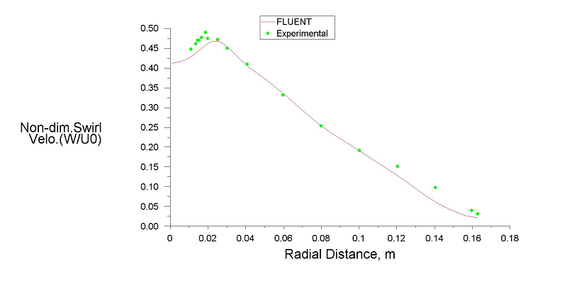
Turbulent flow with a strong swirl component is modeled in an axisysmmetric diffuser. The swirl component of the velocity has a dominant effect on the flow field inside the diffuser.

| Material Properties | Geometry | Boundary Conditions |
|---|---|---|
|
Density: 1 kg/m3 Viscosity: 1.293 X 10⁻⁶ kg/m-s |
Length of the straight inlet section = 25 mm Length of the diffuser (divergent section) = 510 mm Inlet Diameter = 260 mm Outlet Diameter = 440 mm |
Fully developed turbulent profile for velocity, k and ε at inlet (with average axial inlet velocity = 1 m/s) No-slip condition at the walls |