VMFL035
VMFL035
3-Dimensional
Single-Stage Axial Compressor
Overview
| Reference | Density-based solver (Ansys Fluent) |
| Solver | Ansys Fluent |
| Physics/Models | Compressible (transonic), turbulent flow, moving reference frame |
| Input File | axial-compressor.cas |
| Project Files | Link to Project Files Download Page |
Test Case
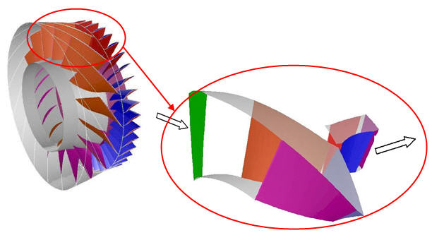
A 3-D model of a single-stage axial compressor is simulated. The flow through the rotor blades is computed in a rotating reference frame, while the flow in the stator blades in a stationary frame. The purpose of this case is to validate the performance of the pressure-based coupled solver for a compressible turbomachinery problem with a mixing plane. The flow is compressible, turbulent and steady.
| Material Properties (for Air) | Geometry | Boundary Conditions |
|---|---|---|
|
Density = Ideal – Gas Molecular weight = 28.966 Specific heat = 1006.43 J/kg-K Viscosity - Sutherland’s law Conductivity - Kinetic theory |
Geometry is as shown in in Figure 91: Flow Domain Number of rotor blades = 16 Number of stator blades = 40 | Rotational speed = 37,500 rpm For Inlet:
|
Analysis Assumptions and Modeling Notes
Steady, turbulent, compressible flow. Ideal-gas law is used for density calculations and kinetic theory for fluid viscosity and thermal conductivity. The standard k-ε model is used for turbulence. Pressure-based coupled solver with a mixing plane at the rotor-outlet/stator-inlet interface.
Results Comparison for Ansys Fluent
The results of the pressure-based Ansys Fluent simulation are compared to the steady state solution from the density-based solver.
Table 28: Comparison of Pressure and Mass Flow Rate
| Target | Ansys Fluent | Ratio | |
|---|---|---|---|
| Pressure at Stator-Outlet (atm) | 1.4725 | 1.48 | 1.005 |
| Mass-Flow Rate at Stator-Outlet (kg/s) | 0.1049 | 0.1076 | 1.026 |


