VMFL032
VMFL032
Turbulent
Flow with Separation Along an Axisymmetric Afterbody
Overview
| Reference |
T.T. Huang, N.C. Groves, “Propeller/stern boundary layer interaction on axisymmetric bodies: Theory and experiment”. David W. Taylor Naval Ship Research and Development Center Report. 76-0113. 1976. | ||
| Solver | Ansys Fluent, Ansys CFX | ||
| Physics/Models | Turbulent flow | ||
| Input File |
| ||
| Project Files | Link to Project Files Download Page |
Test Case
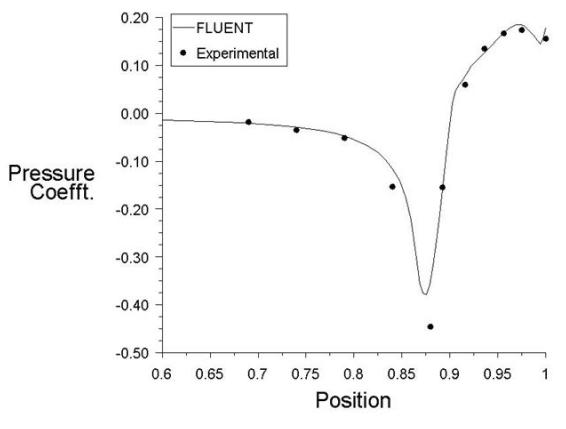
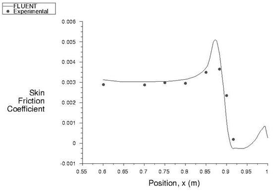
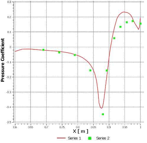
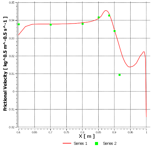
Flow past an axisymmetric afterbody, representing the hull of ship. The flow separates on the rear face of the body.

| Material Properties | Geometry | Boundary Conditions |
|---|---|---|
|
Density: 1 kg/m3 Viscosity: 1 X 10⁻⁶ kg/m-s |
Length of the afterbody = 1.0 m Maximum radius of the afterbody = 0.04556 m |
Fully developed turbulent velocity profile on the inlet normal to axis Axial velocity = 5.9 m/s on the inlet parallel to axis |
Analysis Assumptions and Modeling Notes
The far-field boundary of the domain is set parallel to the axis and is modeled as velocity inlet. Fully developed profile is specified at the transverse velocity inlet.