


This file format can be used to represent boundary surfaces of structured data as unstructured parts. The boundaries defined in this file can come from sections of several different structured blocks. Thus, inherent in the file format is a grouping and naming of boundaries across multiple structured blocks.
Additionally, a delta can be applied to any boundary section to achieve the creation of repeating surfaces (such as blade rows in a jet engine).
Note: There is no requirement that the boundaries actually be on the surface of blocks, but they must define either 2D surfaces or 1D lines. You may not use this file to define 3D portions of the block.
The boundary file is read if referenced in the casefile of EnSight data models, or in the boundary field of the Data Reader Dialog for other data formats. Any boundaries successfully read will be listed in the Unstructured Data Part List of the Data Part Loader Dialog.
The format of the EnSight Boundary File is as follows:
Line (1): Required header keyword and version number. ENSBND is required exactly, but the version number could change in the future.
ENSBND 1.00
Line (2) through Line (NumBoundaries+1): The names of the boundaries to be defined. (Each name must be no greater than 79 .)
For example:
inflow
wall
Chimera Boundary
outflow
Line (NumBoundaries+2): Required keyword indicating the end of the boundary names and the beginning of the boundary section definitions.
BOUNDARIES
Line (NumBoundaries+3) through the end of the file: The boundary section definitions. Each line will have the following information:
bnd_num blk_num imin imax jmin jmax kmin kmax [di dj dk n_ins]
where:
bnd_num is the number of the boundary in the list of names above.(For example: inflow is 1, wall is 2, Chimera Boundary is 3, etc.)
blk_num is the parent
structured block for this boundary section.
imin,imax, jmin,jmax,
        kmin,kmax
are the ijk ranges for the boundary section. At least one of the min,max
pairs must refer to the same plane. A wildcard ("$") can be used to indicate the maximum i, j,
or k value of that block (the far plane). Additionally, negative numbers can be used to
indicate plane values from the far side toward the near side. (-1 = far plane, -2 = one less
than the far plane, etc.)
[di,dj,dk and n_ins] are
optional delta information which can be used to extract repeating planes. The appropriate di,
dj, or dk delta value should be set to the repeating plane offset value, and the other two
delta values must be zero. The non-zero delta must correspond to a min,max pair that are
equal. The n_ins value is used to indicate the number of repeating instances desired. A ("$")
wildcard can be used here to indicate that the maximum number of instances that fit in the
block should be extracted.
All numbers on the line must be separated by spaces.
Finally, comment lines are allowed in the file by placing a "#" in the first column.
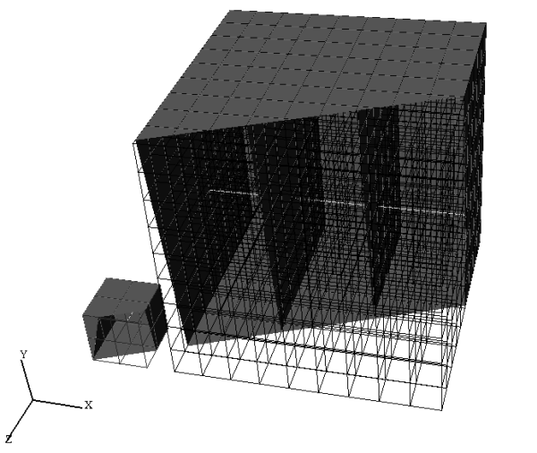
Below is a simple example of a boundary file for two structured blocks, the first of which is a 3 x 3 x 3 block, and the second is a 10 x 10 x 10 block. We will define a boundary which is the front and back planes of each block(K planes) and one that is the top and bottom planes of each block(J planes). We will also define some repeating x planes, namely, planes at i=1 and 3 for block one and at i=1, 4, 7, and 10 for block two. The image below shows the blocks in wire frame and the boundaries shaded and slightly cut away, so you can see the interior x-planes.
The file to accomplish this looks
        like:
ENSBND 1.00
front_back
top_bottom
x-planes
middle lines
BOUNDARIES
#bnd blk imin imax jmin jmax kmin kmax di dj dk n_ins
#--- --- ---- ---- ---- ---- ---- ---- -- -- -- -----
 1   1   1    3    1    3    $    $
 1   2   1    $    1    $    10   10
 2   1   1    $    $    $    1    $
 2   2   1    10   10   10   1    10
 1   1   1    3    1    3    1    1
 1   2   1    $    1    $    1    1
 2   1   1    3    1    1    1    $
 2   2   1    $    1    1    1    $
 3   1   1    1    1    $    1    $    2  0  0  2
 3   2   1    1    1    $    1    $    3  0  0  $
 4   1   2    2    2    2    1    3
 4   2   1    10   5    5    5    5
Interpreting the 12 boundary definition lines:
1 1 1 3 1 3 $ $
defines a part of the boundary called front_back, on block 1, where I=1 to 3, J=1 to 3, and K=3. Thus, the far K plane of block 1.
1 2 1 $ 1 $ 10 10
defines another part of the front_back boundary, on block 2, where I=1 to 10, J=1 to 10, and K = 10. Thus, the far K plane of block 2.
2 1 1 $ $ $ 1 $
defines a part of the boundary called top_bottom, on block 1, where I=1 to 3, J=3, and K=1 to 3. Thus, the far J plane of block 1.
2 2 1 10 10 10 1 10
defines another part of the top_bottom boundary, on block 2, where I=1 to 10, J=10, and K=1 to 10. Thus, the far J plane of block 2.
1 1 1 3 1 3 1 1
defines another part of the front_back boundary, on block 1, where I=1 to 3, J=1 to 3, and K=1. Thus, the near K plane of block 1.
1 2 1 $ 1 $ 1 1
defines another part of the front_back boundary, on block 2, where I=1 to 10, J=1 to 10, and K=1. Thus the near K plane of block 2.
2 1 1 3 1 1 1 $
defines another part of the top_bottom boundary, on block 1, where I=1 to 3, J=1, and K=1 to 3. Thus, the near J plane of block 1.
2 2 1 $ 1 1 1 $
defines another part of the top_bottom boundary, on block 2, where I=1 to 10, J=1,and K=1 to 10. Thus, the near J plane of block 2.
3 1 1 1 1 $ 1 $ 2 0 0 2
defines a part of the boundary called x-planes, on block 1, where I=1, J=1 to 3, K=1 to 3, then again where I=3, J=1 to 3, and K=1 to 3. Thus, both the near and far I planes of block 1.
3 2 1 1 1 $ 1 $ 3 0 0 $
defines another part of the x-planes boundary, on block 2, where I=1, J=1 to 10, and K=1 to 10, then again where I=4, J=1 to 10, and K=1 to 10, then again where I=7, J=1 to 10, and K=1 to 10, then again where I=10, J=1 to 10, and K=1 to 10. Thus, the I = 1, 4, 7, and 10 planes of block 2.
4 1 2 2 2 2 1 3
defines a part of the boundary called middle lines, on block 1, where I=2, J=2, and K=1 to 3. Thus, line through the middle of block 1 in the K direction.
4 2 1 10 5 5 5 5
defines another part of the middle lines boundary, on block 2, where I=1 to 10, J=5, and K=5. Thus a line through the middle of the block2 in the I direction.
Note: The "$" wildcard was used rather randomly in the example, simply to illustrate how and where it can be used.
The use of negative numbers for ijk planes is indicated below - again rather randomly for demonstration purposes. This file will actually produce the same result as the file above.
ENSBND 1.00
front_back
top_bottom
x-planes
middle lines
BOUNDARIES
#bnd blk imin imax jmin jmax kmin kmax di dj dk n_ins
#--- --- ---- ---- ---- ---- ---- ---- -- -- -- -----
 1   1   1    3    1    3   -1   -1
 1   2  -3   -1    1   -1    10   10
 2   1   1   -1   -1   -1    1   -1
 2   2   1    10   10   10   1    10
 1   1   1    3    1    3    1    1
 1   2   1   -1    1   -1    1    1
 2   1   1    3    1    1    1   -1
 2   2   1   -1    1    1    1   -1
 3   1   1    1    1   -1    1   -1    2  0  0  2
 3   2   1    1    1   -1    1   -1    3  0  0  $
 4   1   2   -2   -2    2    1    3
 4   2   1    10   5    5   -6   -6