


The tool allows you to run analysis that are specific to turbomachinery models in an easy and streamlined way. You can access this feature from the menu, the menu, by right-clicking on a part in the part list and selecting the option, or even from the tab. When the option is selected, the tool opens.
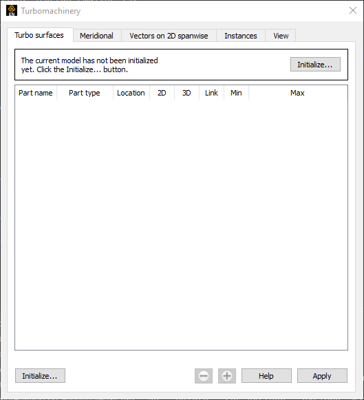
The panel contains five tabs: Turbo surfaces, Vectors on 2D spanwise, Meridional, Instances and View. The first three tabs allow you to create new parts and variables for the analysis. The latter tabs allow you to improve the visualization of the model.
Any model has access to the Turbomachinery analysis tool, regardless of data format. However, if the data is in CFX format, some meta information will be passed directly into EnSight making the initialization process easier. For all other data formats, you will be required to manually enter all the initialization information.
The current Turbomachinery analysis in EnSight makes a few assumptions about the geometry of the model. This limits the capabilities or performance of the feature.
If the dataset represents an entire 360 degrees model (no periodic conditions in the direction perpendicular to the axis of rotation) and the components complete a rotation of more than 180 degrees, the feature will not be able to complete the step.
If the dataset contains one or more components that has a twist of more than 180 degrees in the direction of the rotation axis, then the step will take longer to complete. The feature will function, but initialization will take significantly longer.
Note: The creation of Turbo surfaces, Meridional part and Vectors on 2D spanwise variables is not allowed on the Mac platform. Only the Instances and View tabs are available.
Finally, the Turbomachinery feature does not currently work with case linking. If working with multiple cases and Turbomachinery, make sure the currently active case (from the menu) corresponds to the one you want to analyze. The Turbomachinery user interface will only show the settings and Turbo surfaces corresponding to the currently active case.
The Turbomachinery tool will automatically detect if initialization has already been performed when launched. In the latter case, or if you wish to reset the initialization, click in the Turbo surfaces or in the Meridional tab. This will prompt the Initialization dialog.
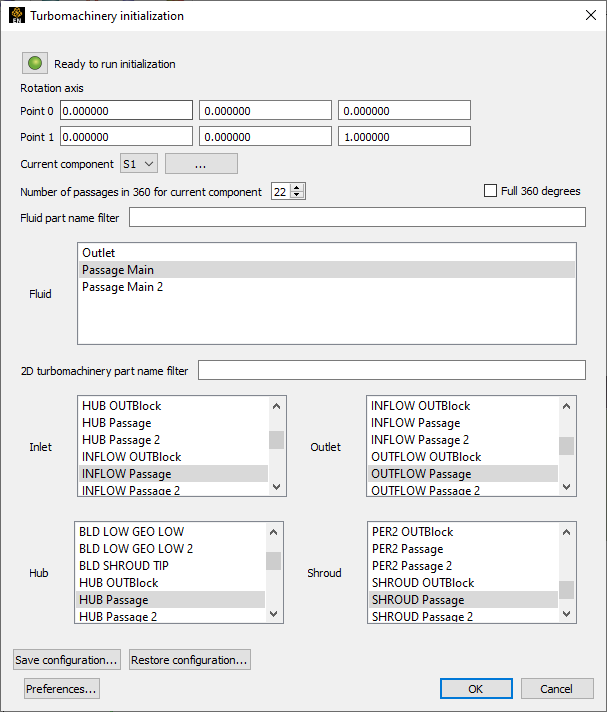
For CFX models, the Turbo initialization dialog will have most of the entries already filled in. For all other data formats, you will be required to enter all the information for initialization by hand. The following table will explain all the entries.
| Point 0 and Point 1 | X Y Z coordinate values for the points that define the axis of rotation. |
| Current component | Pull down menu that allows you to select a component for the selection process. The button brings up a new menu with the list of all components. See Component List for more details. |
| Number of passages in 360 for current component | Sets the number of passages for the selected component in a 360 degrees model. |
| If the dataset represents the entire 360 degrees model, toggle this on. Having this toggled off will not result in a failure of the feature, but it will make the step an order of magnitude slower. | |
| Fluid part name filter | Filter for the part names in the Fluid list (see below). The filter is case sensitive. |
| Fluid | List of 3D parts. Select at least one of them as the fluid part corresponding to the current component. |
| 2D turbomachinery part name filter | Filter for the part names in the Inlet, Outlet, Hub and Shroud lists (see below). The filter is case sensitive. |
| Inlet, Outlet, Hub, Shroud | List of 2D parts. Select at least one part for each list to mark the Inlet, Outlet, Hub, Shroud for the current component. If multiple parts are selected for each turbomachinery type, the process will merge them into a single part. |
| Save the current initialization settings into a .trb file. For details on this file format, see Turbomachinery Initialization File Format. | |
| Restore the initialization settings from a .trb file. For details on this file format, see Turbomachinery Initialization File Format. | |
| Opens the Preferences dialog. See Preferences. |
If the initialization settings are complete, for example, each component has at least
one Fluid, Inlet, Outlet,
Hub and Shroud part selected, then a green
circle will appear at the top, with the label Ready to run
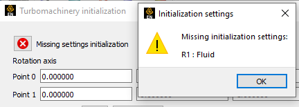
initialization. If any setting is missing, the green circle will be
replaced by a red cross, and clicking it will open a dialog that lists which elements are
missing from the Turbo initialization settings. See Figure 5.168: Missing Elements for Each Component.
Once everything has been set, click to run the turbomachinery initialization process. No changes will appear in the EnSight user interface, however, the program is now ready to run Turbomachinery analysis. See Turbo Surfaces Types, Meridional Tab and Vectors on 2D Spanwise Tab for more details.
In the Turbomachinery initialization dialog, you can click on the button next to the Current component field to bring up the Turbomachinery components dialog.
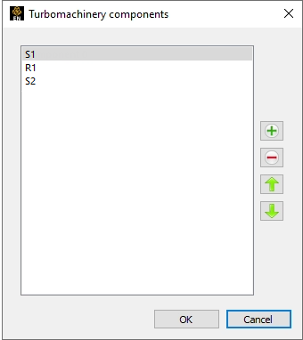
The dialog contains a list of the available components. You can add / remove a component by using the and button. A component can be renamed by double-clicking the component name in the list. Spaces are allowed inside a component name, but not as first or last character.
Note: The order of the components is important and should match the geometrical order in the model itself, from the furthest upstream first, to downstream. Change the order of a component by selecting it in the list and then using the up or down arrows.
During the initialization process EnSight will try to extract as much information as possible from the dataset itself. To achieve that, EnSight will check if the parts are already tagged as belonging to a specific turbomachinery component and, in this case, which turbomachinery type they are assigned to (, , , or ). It is possible that a part has been tagged for a specific component, but no turbomachinery type has been associated with it. If this is the case, EnSight will use the mapping presented in the Preferences dialog to try to match the part to a turbomachinery type.
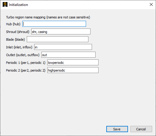
EnSight will do the matching using the part name and the strings associated with each turbomachinery type. The match is case insensitive. You can modify the strings used for this process via the fields in the Preferences dialog. Saving this dialog will preserve this setting among different EnSight’s sessions as long as they are all run on the same machine with the same version of EnSight.
EnSight will try to automate the initialization settings as much as possible by extracting information directly from the dataset loaded. It is possible that some initialization is not set correctly. It is suggested to verify them before running the initialization, even if the Initialization panel reports no issues. Some common issues are:
The number and name of the components are correct, but not their order.
If there is a component that spans multiple fluid domains, multiple parts can be selected for the inlet and the outlet, instead of a single part.
Note: The auto initialization is only possible for CFX datasets. If the data is in another format, you will need to manually input all the information in this panel.
The Turbo surfaces tab allows you to create new parts specific for turbomachinery analysis.
Note: This tab is not available on the Mac.
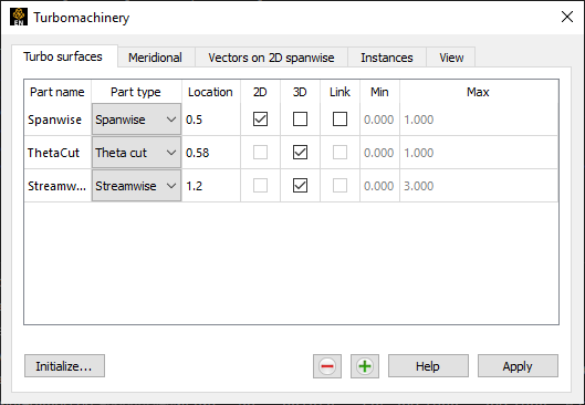
After initialization has successfully completed, the , and button will become available. The button adds new parts to the table which are then created. This will create a new empty row appear within the table. For each entry, the following columns are available:
| Part name | The name of the turbo surface part. |
| Part type | Three options are available for the part type: , and . See Turbo Surfaces Types for more information on each of these options. |
| Location | Location of the clip in the RTA space. See Turbo Surfaces Types for more information. |
| 2D | Toggle on if the part should be visible in 2D space. This will create a new
viewport where only the 2D turbo part will be visible. Note: This option is only allowed for a part. |
| 3D | Toggle on if the part should be visible in the main 3D viewport. This is option is only available for the and part types. |
| Link | Available only for the part type. It allows a 2D turbo part to be linked with a 3D turbo part. Changing one of their location will automatically update the location of the other. Only two parts can be linked at any time, and must be a 2D Spanwise part. |
| Min | Minimum of the range valid for the Location field. It is 0.0 for all part types |
| Max | Maximum of the range valid for the Location field. For and part types (1.0). For the part type, it corresponds to the number of components that have been initialized. |
Once you have set the parts and their settings, use the button to begin creating them. The new Turbo surfaces part will now appear in the Parts list. Double-clicking them within the Parts list, or right-clicking and selecting will bring up this dialog again.
You can modify the settings of these parts by changing the entries in this table and then clicking the button.
You can delete a Turbo surfaces part by either deleting it manually from the Parts list, or selecting it in the table from the Turbo surfaces tab, clicking on the button and then pressing .
When loading a turbomachinery model, it is shown in the XYZ space, which is the ideal space to display the details of the geometry, but not the best space to understand the physics of the flow. For this type of analysis, using the RTA space is recommended. This is defined by the following coordinates:
R: The radial coordinate. This is the normalized distance between the hub (R = 0) and the shroud (R = 1).
A: The axial coordinate. This is the normalized distance between the inlet (A = 0) and outlet (A = 1). Sometimes it is more convenient to work with a not normalized axial coordinate, i.e. the distance from the inlet along the inlet-outlet direction vector. We refer to this non-normalized coordinate as M (meridional coordinate).
T: The theta coordinate. This is the rotation angle in the plane perpendicular to the rotation axis.
Three Turbo surfaces types are available to represent the clip of the model in this RTA space:
The type is a clip at a constant R value. When displayed in 3D, the part will be shown inside the original model, sweeping from the hub to the shroud. When displayed in 2D, the part is shown in a new 2D viewport in the RTM space. Since R is constant, the axes will be Theta (T) and M.
Note: The minimum value of the spanwise clip is set to 1e-5, while the maximum value is set to 0.99999. Taking a spanwise clip at such values can result in a part with gaps, depending on the geometry of the model. This is due to numerical precision issues at the edges of the fluid domain.
The type is a clip at a constant A value. The axial coordinate is normalized for each component, which means that A = 0 corresponds to the inlet of the first component, and A = n corresponds to the outlet of the last component, where n is the total number of components that have been initialized.
The type is a clip at a constant T value. The Theta angle value is normalized.
The Meridional tab allows the user to create a meridional cut specific for turbomachinery analysis.
Note: This tab is not available on the Mac.
After initialization has been run, you can create a Meridional part via this tab. Set the properties and press to create the part. If a Meridional part already exists, you can modify its settings by changing the values in this menu and then pressing .
Note: EnSight will create one Meridional part for each component in the model. If there are multiple components, these newly created parts will be placed under a Meridional part group. If there are multiple components, there will be a gap between the Meridional parts corresponding to each component. The size of this gap can be reduced by increasing the number of sample points, but can never be completely eliminated.
A Meridional part is a cut through the fluid domain taken at a fixed Theta value in the RTA space. In this space, the part has a regular grid with a fixed number of points in both R and A direction. When coloring the part by a variable, EnSight will calculate a new field where the value at each (R,T,A) point of the meridional part corresponds to the interpolation of that variable along the path that has the same (R, A) values, but Theta spanning from 0 to 1. The new variable created via this interpolation will be available in the EnSight variable list.
Note: These newly created variables are highly sensitive to large gradients in the axial direction. This will be noticeable near the boundaries between two components. This behavior is the result of the sampling algorithm and is to be expected.
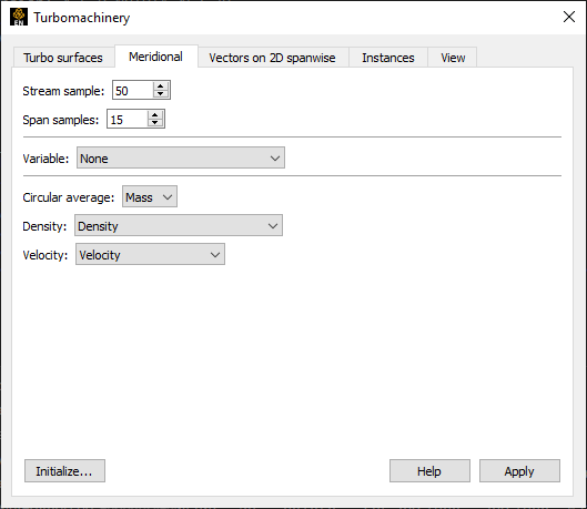
All these parameters are set via the entries in the tab.
| Stream sample | Number of points for the Meridional cut in the axial direction. |
| Span sample | Number of points for the Meridional cut in the radial direction. |
| Variable | List of variables to choose from for the interpolation. Only scalar variables are supported. |
| Circular average |
Algorithm to use for the interpolation of the variable. Two options:
|
| Density | List of scalar variables to choose from for the Density field. This is available only if is selected as the Circular average algorithm. |
| Velocity | List of vector variables to choose from for the Velocity field. This is available only if is selected as the Circular average algorithm. |
When creating or modifying a meridional part, if the total number of points (for example, stream sample X span sample X number of components) exceeds 200000, a warning message will appear. This informs you that such a request might take some time to be executed in EnSight.
Once the meridional part is created, it will be displayed in a new 2D viewport in the RTA space, with R as the horizontal and A as the vertical axis.
The Vector on 2D spanwise tab allows you to create a vector variable corresponding to the projection in the RTA space of the input vector field.
Note: This tab is not available on the Mac.
These created variables can be used to visualize their input fields on the 2D spanwise surface.
Note: Should you attempt to directly visualize the original vector field on the 2D spanwise part, the resulting values will show the cartesian representation of the field instead of the projected RMT values.
Therefore, you need to manually do the projection via this tab and ensure they use the correct variable when working in the turbomachinery space.
This tab can only be executed if you have already performed the turbomachinery initialization step. Should this not be the case, the button will not be available.
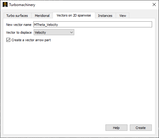
The following parameters are set via the entries in the tab.
| New vector name | The name of the projected vector variable to calculate. |
| Vector to displace | List of vector variables to choose from for the projection operation. |
| If toggled on, EnSight will create a vector arrow part on the 2D spanwise part with the newly created variable. This field is only available with 2D spanwise parts. |
Note: The new projected vector variable is only defined on the 2D spanwise part. If a vector arrow part is created from this variable, it cannot be of Curved type, since this setting would require the variable to also exist on the 3D fluid domain the vector arrows would propagate into.
The Instances tab allows you to quickly set up the rotation attributes on parts to correctly visualize the entire turbomachinery model. This tab can be used regardless of initialization status.
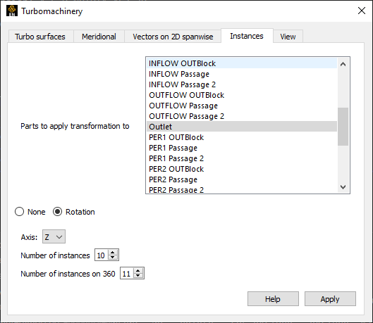
By default, is off on all parts. Select one or more parts from the Parts to apply transformation to list. Toggling on will grant you access to the rotation symmetry settings. If initialization has been completed, EnSight will set the rotation Axis, the Number of instances and Number of instances on 360 on the model according to the initialization settings. These values can be overwritten. Click to have the new instances created.
Note: This will only create the visual symmetry. For example, the new parts that appear in the main viewport will be client only.
The View tab allows you to quickly visualize the turbo parts.
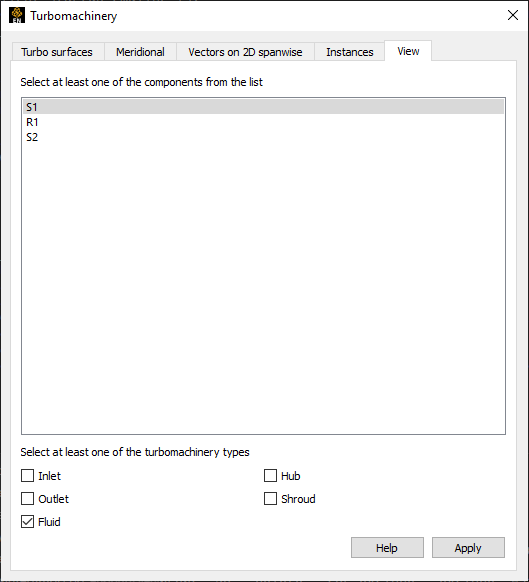
While this functionality can be run regardless of initialization status, it is more useful after initialization. Select at least one of the components from the list shows all the turbomachinery components. Select at least one of the turbomachinery types presents a toggle for each turbomachinery type (, , , , ). Select one or more components and toggle one or more turbomachinery types, then hit . Only parts that correspond to the selected components and are of the selected turbo types will be visible on the main viewport. This feature allows you to verify the geometry of the problem quickly and easily.