


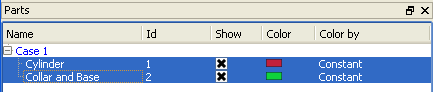
Select the parent parts.
Click the Displacements icon.
Select the nodal variable to use.
Important: Can only use nodal vector variables
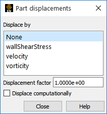
If desired, enter a value for the Displacement Factor and press Return.
For speed and memory, default is visual displacement only. If you desire to use the displacement in any calculations then toggle on , which will do server-side displacements.
Note: Your changes made are immediate. Specifying a displacement does not create a new part, it merely sets the displacement for the selected parts.
Server side displacements have more detailed found in the Create/edit dialog.
First read in your model, build the desired parts, and activate the model variable (not computed variables) representing displacement.
Select the desired parts in the Parts list.
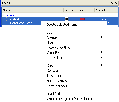
Right click on them and select
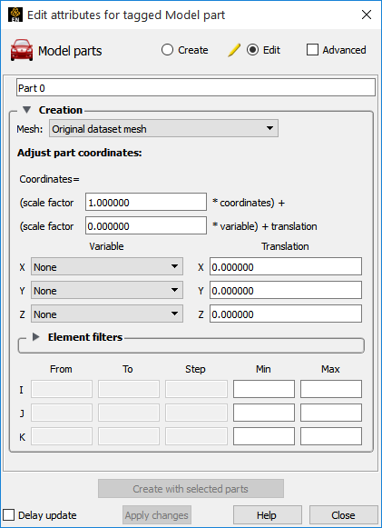
Set any desired entire geometry scale factor * coordinates) +.
Hit a carriage return.
Set the scale factor *variable) + translation for any desired displacement variable.
Hit a carriage return.
Set the nodal displacement model Variable and any desired translation for each X, Y and Z component.
Hit a carriage return.
Note: It is possible to displace in each component direction by a different variable and to translate by a single value in each direction. It is also possible to scale the entire geometry by a factor.
Displacements applied in this manner actually modifies the geometry on the server (not just the visual representation on the client). Any queries or computations will reflect this modified geometry. For example an area or volume calculation will now use the displaced values.