It is sometimes useful to display just the nodes of a line clip. Click Node, elements and line pulldown lower in the Create/edit Parts dialog in the advanced mode and you can change the display such that only nodes (not lines or elements) are displayed. The nodes can be dots, crosses, or spheres. If displayed as crosses or spheres, the size (radius) can be constant or scaled by the value of a variable. See Set Attributes for more information.
Clip of a 2D Part Using the Line Tool
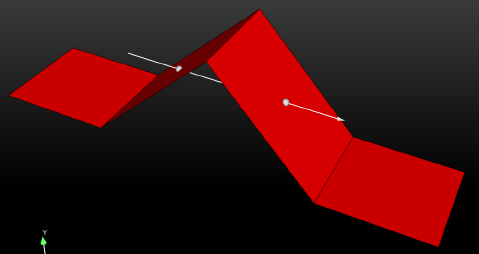
A Clip of a 2D part using a line tool that is perpendicular to the 2D part surface will give you an empty part. The reason is as follows. In the past, EnSight would sometimes fail to clip a 2D part due to numerical tolerance errors when the line tool wasn't numerically exactly on the surface. To work around this numerical issue, the line tool is now projected onto the 2D part, which results in a line clip projected onto the surface except for a perpendicular line tool. For example, suppose you have a geometry shown below with the line tool positioned as indicated.
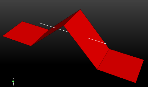
If you create a clip using the line tool, you will get the following line clip, which is a projection of the line tool onto the surface of the part.
Note: The clip is at one of the infinitely many possible projection planes through the line tool. If you want to control the projection plane, clip with the plane tool rather than doing a line clip.
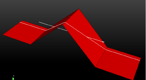
The algorithm used to decide which projection plane to use may not be to your liking, and you may wish to only have the points where the line tool intersects the part. To do this, set an environmental variable which will give the point intersection of the line tool and redo the clip that results in a clip part with two points, as shown below.
setenv
        ENSIGHT_2D_MESH_LINECLIP_POINT_OPTION 1