


Much of the strength of EnSight derives from its flexible and powerful part creation mechanism. Since virtually every task you perform in EnSight will involve some form of part manipulation, it is vital to understand these concepts.
In EnSight, a part is a named collection of elements (or cells) and associated nodes. The nodes may have zero or more variables (such as pressure or stress) currently defined at the node positions. All components of a part share the same set of (such as color or line width).
Parts are either built during the loading process (based on your computational mesh and associated surfaces) or created during an EnSight session. Parts created during loading are called model parts. Model parts can also be created during an EnSight session by performing a copy on other model parts or performing a load operation on the part.
All other parts are created during an EnSight session and are called created or derived parts. Created parts are built using one or more other parts as the parent parts. The created parts are said to depend on the parent parts. If one or more of the parent parts change, all parts depending on those parent parts are automatically recalculated and redisplayed to reflect the change. As an example, consider the following case. A clipping plane is created through some 3D computational domain and a contour is created on the clipping plane. The contour's parent is the clipping plane, and the clipping plane's parent is the 3D domain. If the 3D domain is changed (for example, the time step changes), the clipping plane will first be recalculated, followed by the contour. In this way, part coherence is maintained.
This article is divided into the following sections:
Where Parts Are Created and Maintained
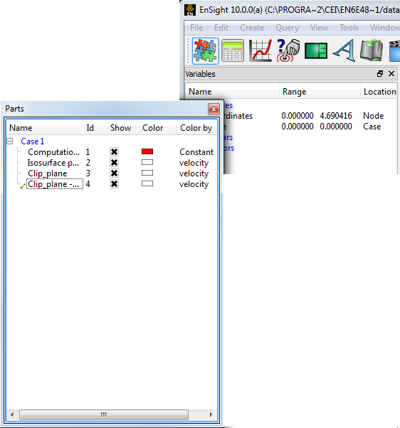
Both model parts as well as all derived parts are displayed as items in the Parts list. There are several ways that the Parts list can be displayed, the default looks something like:
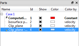
Case number (important when multiple datasets have been loaded).
P indicates Parent of currently selected part.
Part numbers.
Currently selected part.
Part description.
Part being edited in the Feature Panel is marked with a pencil icon.
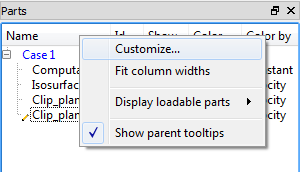
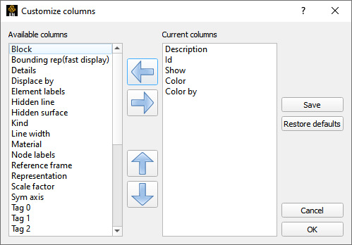
If you right click on any of the columns of the Parts list you can which columns of data will be shown in the list. In the resulting pop-up dialog you can select from either the left or right columns and use the left/right arrow buttons to add or remove the column to the Parts list. You can also change the order of the columns in the Parts list by selecting the attribute in the right panel and using the up/down arrows to change the order.
will keep the settings for the next time you run EnSight while will apply the changes but not save them.
See Load Multiple Datasets (Cases).
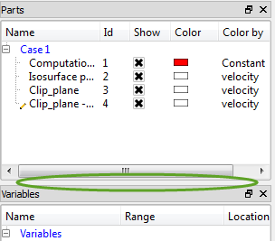
The part list can be resized by grabbing the boundary between the panels (the mouse cursor will change to show a resize handle if you’re in the right spot).
You can also grab the Parts panel by the title bar and drag the entire panel out from its user interface dock location.
There are several ways to easily select multiple parts. If you wish to select all parts in a Case (which is really just a group) you select the blue Case line in the Parts list. You can also perform part selection operations via the right click pulldown menu.
There are a number of right click capabilities for a part. The right click works in both the Parts list as well as in the graphics window.
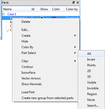
You delete a part by either utilizing the right click pulldown, or you can select the part and hit the Delete key in either the Parts list or in the graphics window.
You can create part groupings by selecting one or more parts and creating a group from the right click pulldown.
Once a part group has been created you can drag and drop parts into/out of the group.
Also, Items in the Parts list can be selected using standard selection methods:
The mechanism for creating derived parts is largely the same regardless of part type:
In the Parts list, select the part(s) to use as parents.
Select the desired creation feature. This can be done via the Feature Icon Bar if the required creation feature is visible or can be selected via the Create pulldown from the main interface or by right-clicking the part (either in the Parts list or in the graphics window). Any one of these will bring up the Feature Panel for the part type in question in create mode.
Set any desired options in the Feature Panel.
Click the button to create the part.
There are also right-click methods to create parts. These go through the same steps as above but may make some assumptions to quickly create a part.
The example below shows Isosurface part creation:
Select the parent part(s).
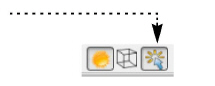
Select the Isosurface Feature icon.

Select the Variable to use.
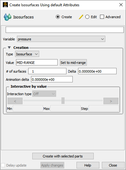
Select an appropriate isovalue under the Value field. (Often there is a sensible default).
Click .
The following table provides information on the available part types in EnSight:
| Part Type | Symbol | Feature Icon | Description |
|---|---|---|---|
| Clip | 2 |
 | A surface or line resulting from a clip of parts using an IJK, XYZ, or RTZ surface of the parts; or a clip of other parts using the Line, Plane, Box, Cylinder, Sphere, Cone, or Surface of Revolution tool; or a clip of other parts by revolving an existing 1D part. |
| Contour | C |
 | Lines of constant value on 2D elements. |
| Developed Surface | D |
 | A planar surface derived by unrolling a surface of revolution (for example, unrolling a clip created with the Cylinder tool). |
| Elevated Surface | E |
 | A part created by scaling a 2D part (in the direction of the local surface normal) based on the value of a variable. |
| Isosurface | I |
 | A surface of constant value through 3D elements. |
| Model | M |
 | An original part ( i.e. loaded from a disk file) or created through some operation (for example, copy or extract) on a model part. |
| Particle Trace | T |
 | A part consisting of the paths taken by one or more massless particles as integrated through a vector (typically velocity) field. |
| Profile | P |
 | Plot of a variable along a line (the 2D counterpart to an elevated surface). |
| Vector Arrow | V |
 | A part consisting of a set of arrows showing direction and magnitude of a vector variable. |
| Subset | S |
 | A part created by node and/or element label range(s) from model part(s). |
| Tensor Glyph | G |
 | A part consisting of tensor glyphs showing direction and relative magnitude of the eigenvectors of a tensor variable. |
| Material Part | A |
 | A part created according to the intersection of or domains of material values. |
| Vortex Core | X |
 | A part consisting of line segments down the center of flow vortices. |
| Shock Surface/Region | K |
 | A part consisting of the surface or volume elements where shock is higher than a threshold. |
| Separation/Attachment Line | L |
 | A part consisting of line segments on a surface where flow separation and attachment is occurring. |
EnSight provides several powerful part operators. These operations are accessible from the Edit → Part submenu or from right-click on a part.
|
Copy |
The copy operation creates a dependent copy of another part. The part is created on the client and is not known to the server. The new part has its own set of (except for representation), but shares geometric and variable data with the original. One of the best reasons to create a copy is to show multiple variables on one part at the same time in a side-by-side configuration. The copies can be moved independently since each new copy is automatically assigned a new frame . See Copy Parts for more information. |
|
Clone |
This operation will create a new part identical to the one(s) being cloned. They are not dependent on the part cloned for model parts but are dependent on the same parent parts in the case of created parts. See Clone a Part for more information. |
|
Group |
This operation will collapse the selected parts into a new umbrella part. Grouping is most often used to combine a series of parts into a single entity for ease in handling. No new part is created - only a hierarchy in the Parts list. The operation is reversible through the Ungroup command. See Group Parts for more information. |
|
Delete |
The delete operation completely removes not only the currently selected parts, but also any parts derived from the selected parts. See Delete a Part for more information. |
|
Extract |
The extract operation is closely tied to part representations. Extract creates a new dependent part using only the geometry of the current representation of the part. For example, if the current representation of a part consisting of 3D elements is Border, the result of extraction will be a part consisting of all unshared 2D elements (the surface). Extract is most often used to reduce the amount of information for a part (for example, for faster display or for geometry output ) or to create a surface shell part - perhaps for subsequent cutting - of a 3D computational domain. See Extract Part Representations for more information. |
|
Merge |
Merge creates one new dependent part from one or more selected parts. The original parts are unchanged. If only a single part is selected for the operation, merge will create a true copy of the part (as opposed to the shallow copy that the Copy operation creates). Merging is most often used to combine a series of parts into a single part for ease in handling (such as attribute setting). See Merge Parts for more information. |
All parts have numerous options that control behavior and display. Although many can be controlled either through the Part Quick Access Icons or the right mouse button options, complete access is provided by the Feature Panel. Part and the Feature Panel are covered in detail in Set Attributes.
Part creation occurs on either the EnSight client or the server. Since the data that is available on the client and server are different, it is useful to understand where parts are created and where the data is stored. For example, you can only perform a query operation for parts that are stored on the server. The following table provides this information for each part type:
In the last column, depending on representation means the current visual representation for the part. For example, if the part's visual representation is Not Loaded, then no data is currently present on the client.
With some datasets that contain many parts, it is important to maintain the connection between a part as displayed in the Graphics Window and the corresponding item in the Parts list. EnSight shows the selected parts as highlighted. To toggle this feature on or off, click on the Highlight Selected Parts toggle.
You can rapidly cycle through items in the Parts list using the up/down arrow keys on your keyboard. Select any item in the list and then press the up arrow (to move to previous entries) or down arrow (to move to subsequent entries). This is particularly helpful when used in conjunction with the Part(s) Selected Highlighting (as described above) to quickly locate a part of interest.
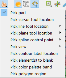
You can select parts in the Parts list using a single left click on the part in the graphics window. This should work unless your single-click settings has been changed from the default Pick Part. To change it back to Pick Part, Edit → Preferences and click on Mouse and Keyboard. You can also select parts in the Graphics Window by picking using P. Select Pick Part from the Pick pull-down. In the Graphics Window, place the mouse pointer over any portion of the desired part and press P. If you hold down Ctrl at the same time, the part is added to the list of currently selected parts.
A quick way to create parts using the default settings is to right-click on a part in the graphics window. A pulldown selection will appear that will give you the option to create a Contour, Isosurface or Vector Arrow part using the default settings using the parent as the part you right-clicked.
Selected parts can be written to disk and loaded in a future session. Select File → Save → Geometric Entities ... You have the option of saving either in EnSight format, STL format, or other user-defined formats. See Save Geometric Entities for more information.