The following topics are included in this section:
On startup, EnSight creates a default frame - frame 0 - located at 0,0,0 of the right-handed "world" or model coordinate system and aligned with the X, Y, Z axes. All parts (model and newly created) are assigned to frame 0 initially. Frame 0 is special in that it cannot be repositioned or deleted.
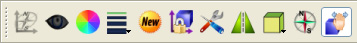
Note: Frame operations are reserved for the expert user. By default, the Frame Feature icon is not enabled. To enable it, go to → , and toggle Frames on.
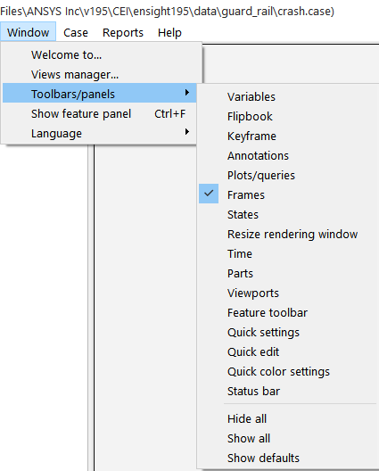
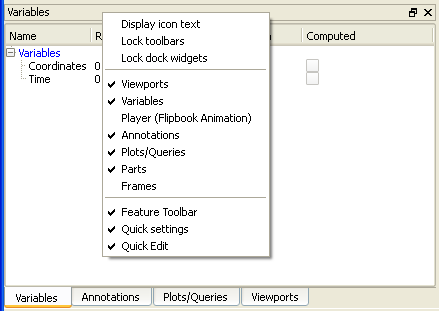
Alternatively, one can right click on the head of the List Panel section, and toggle on.
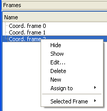
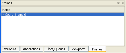
After which, the Frames List Panel will be available, default Coord. frame 0 is listed, and the operations described below can be performed.
Frames are selected either by clicking a visible frame axis triad in the Graphics Window (implying that the frame triad had to previously been set to be visible) or by selecting the desired frame in the Frames list panel. Any frame operation (such as setting) acts on the currently selected frame(s).
The EnSight positioning tools (Cursor, Line, Plane, and Quadric tools) are always positioned with respect to the currently selected frame. If more than one frame is selected, frame 0 is the reference frame for tools. If you have tools visible, you will notice them changing position as the selected frame is changed.
EnSight implements computational periodicity (such as rotational symmetry) as an attribute of frames. If a frame has symmetry enabled, all parts assigned to the frame will be duplicated as specified by the particular type of symmetry.
A frame axis triad consists of three lines representing the X, Y, and Z orientation vectors plus labels. Selected frames are highlighted in the Frames list.
EnSight does not support hierarchical frames: you cannot assign a frame to another frame to implement nested transformations. All frames are embedded in the same world coordinate system ( i.e. frame 0).
In general, you have to explicitly create new frames. However, EnSight will automatically create a new frame each time you create a copy of a part and assign the copy to the frame.
To create a frame:
Decide if you want the new frame to be set to the default 0,0,0 position (same as the model coordinates), or whether you would like to have it centered on some selected part(s). If the former, make sure no parts are selected in the Parts list. If the latter, select the desired part(s) in the Parts list.
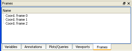
Either select an existing frame in the Frames list panel and hit the New Frame icon.

OR
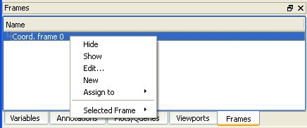
Right click on an existing frame in the Frames list panel, and select .
The new frame also becomes the currently selected frame.
There are two ways to select frames. You can select frames in the Frames list panel, or click the frame axis triad in the Graphics Window (if the triad is visible).
To select frames using the Frames list:
Click the Frames tab, to show the Frames list panel, if it is not already shown.
Select the desired frames in the list.
You can use standard techniques, such as shift-click to extend a selection or Ctrl-click to add to the list (or de-select an item if already selected).
To select frames in the Graphics Window:
Note: This implies that the frame triad(s) are already visible. If they are not, you will need to do your first selection using the Frames list as described above. Then make the frame triad(s) visible by toggling on the Axis visibility icon.
You can now:
Position the mouse pointer over the frame axis triad (the lines – not the XYZ labels) and click the left mouse button.
You can extend a selection of frames by holding down the Ctrl key as you click on frames.
To assign a part to a frame:
Select the desired part(s) in the main Parts list.
Select the desired frame (as described above).
Click the Assign selected part(s) to selected frame icon to assign the part(s) to the frame.

OR
Right click on the desired frame and select → .
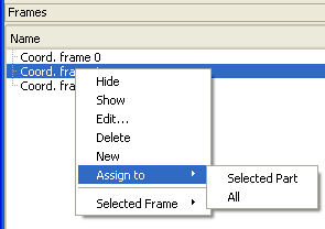
Note: You can easily assign all parts to a frame using the latter method A message is printed to the EnSight Message Window (found under the Information display icon), confirming the assignment.
You transform a frame (and all parts assigned to it) when you perform any transformation while in Frame Transform mode. Frame Transform mode is set by default.
You toggle between it and Frame definition mode for the selected frame(s) using the Transform/Define frame(s) icon on the Quick Action Icon Bar.

or in the Create/edit Frames dialog.
Important: Generally one should only use the Define mode while first creating and orienting the frame. Therefore before any parts are assigned to it. Thereafter one should ensure that they are using Transform mode. If you do this, you will avoid error and confusion in the use of frames.
To transform in Frame Transform mode:
Select the desired frame(s) (as described above).
Ensure that the Transform/Define frame(s) icon is set to the Transform mode.

This can alternatively be done in the Create/edit Frames dialog, where radio buttons show the state.
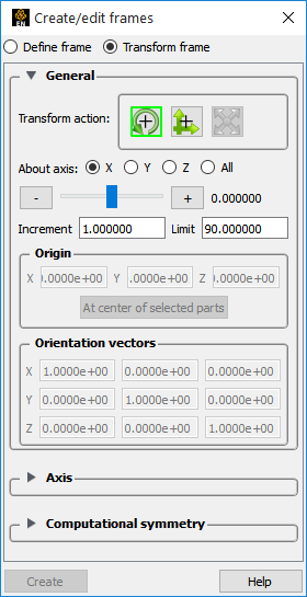
Perform the desired transformation either interactively (using the Transformations Control icons and the mouse in the Graphics Window) or via the Transform Action in the General section in the Create/edit Frames dialog.
See Rotate, Zoom, Translate, Scale for more information.
See Rotate, Zoom, Translate, Scale.
Frame transforms are implemented as a transformation applied with respect to the frame's position and orientation. At times you will need to modify the position and orientation of the frame independent of the parts assigned to it. This is done while in Frame Definition mode. You have been shown how to enter Frame Definition mode above.
Important: You cannot change the frame definition if you have performed any frame transformations (if you attempt to do so, a dialog will remind you). Any frame definition must be applied prior to a frame transformation. If you have already made frame transforms you can clear them by returning to frame transform mode and using the Reset Tools and Viewports dialog (click Reset... to open).
To transform the Frame Definition:
Select the desired frame(s) (as described above).
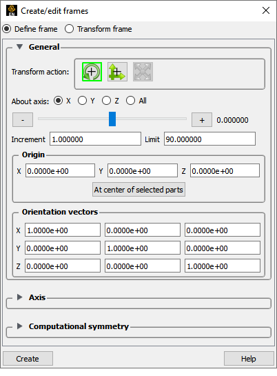
Ensure that the Transform/Define frame(s) icon is set to the Define mode. This can alternatively be done in the Create/edit Frames dialog, where radio buttons show the state.

Perform the desired transformation either interactively (with the mouse in the Graphics Window) or via the Transform Actions in the General section in the Create/edit Frames dialog.
To translate the frame interactively, move the mouse pointer into the Graphics Window and click and drag the left mouse button. To rotate the frame interactively, click and hold the left mouse button on one of the frame axes and drag the mouse. Clicking on the X axis will rotate the frame about its Y axis. Clicking on the Y axis will rotate the frame about its X axis. Clicking the Z axis will rotate about both X and Y.
(Use the Transform Action in the General section to rotate about the Z axis only.)
You can also edit the frame's definition explicitly using the Transformation Editor dialog:

Click the Frame Location icon. This opens the Create/edit Frames dialog in Frame Definition mode.
Select the desired frame(s).
If desired, enter new value(s) in the XYZ fields to change the frame’s origin (remember to press Return).
If desired, enter new value(s) for the orientation vectors (remember to press Return).
Note: The orientation vectors are normalized afresh when you press Return.
The frame transform can be reset back to the default position and orientation by using the Reset Tools and Viewports dialog. To clear the frame transform:
Select the desired frame(s) (as described above).
Make sure the Transform/Definition icon is set to transform.
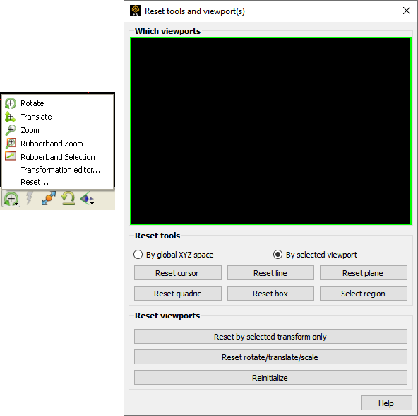
Click the button in the Transformation Control area to open the Reset Tools and Viewports dialog.
In the Reset Tools and Viewports dialog, click the desired button:
Reset By Selected Transform Only: clear only the transformation component currently selected (for example, rotate or translate) in the Transformation Control area.
Reset Rotate/Translate/Scale: clear all transformation components.
See Reset Tools and Viewports for more information.
Frames can be displayed with a variety of options:
Select the desired frame(s) (as described above).
Set the desired attribute as described below:
Click the Axis Visibility toggle to toggle display of the axis triad of selected frames on or off.

Click (opens the Color Selector) to set the color for the axis triad of selected frames.

Click the Frame Line Width pull-down to set the line width for the axis triad of selected frames.

Click the Axis icon to set axis (described below).

Click Computational symmetry icon to set translational, rotational, or mirror symmetry (described below).

To adjust the length of the frame axes, enter new values in the X, Y, and Z Length fields and press return.
To display a series of evenly spaced labels along an axis (showing distance from the axis origin), toggle on the applicable button, enter the desired number of labels in the # of field, and press Return.
To choose the type of computational symmetry (translational, rotational, mirror).
Once the type is chosen, appropriate controls will open for that type.
If your data is not Case Gold format then you can interactively chose to use a Periodic File. If it is Case Gold then you must enter the matchfile name in the Case file
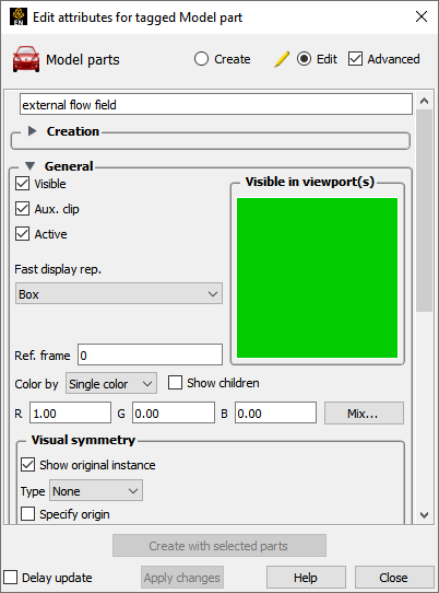
You can determine what frame a part is assigned to (and change it) by opening the Parts Feature Editor:
Open Create/edit Parts by double-clicking on the desired part.
OR
Right click on the part in the Parts list, and select
Open the General turndown.
The part’s current frame number is shown in the Ref. Frame field. You can reassign a part to a different frame by entering a new value and pressing Return.