


The surfaces of parts are rendered using surface properties (such as color and highlight properties) interacting with one or more light sources. But default there is a directional light located along the line of sight. This at the viewer light source can't be modified, that is, it is always a directional light pointing in the camera view direction. However, you can turn it off or adjust it's color or light intensity. In addition to this first light source, there can be up to seven additional lights of various types and positions. These lights are taken into account in the graphics window and for ray traced images.
There are various reasons to define additional light sources. However, the primary and most common use is to define lights for the ray tracer, such that shadows and reflectivity can be shown in the scene.
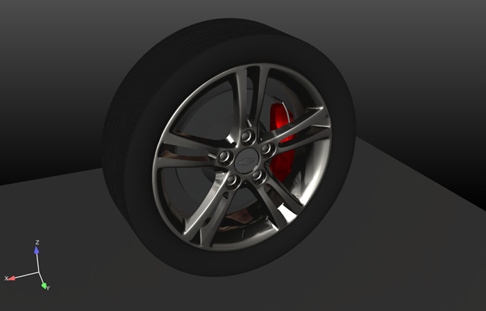
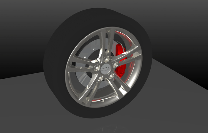
Here is a scene showing the image produced in the graphics window. It has a single default light source, that is, the light is at the camera position shining in the camera view direction. If we ray trace this, you get the following image:
As you can see, you have no shadows in the scene because the light and viewer directions are co-aligned.
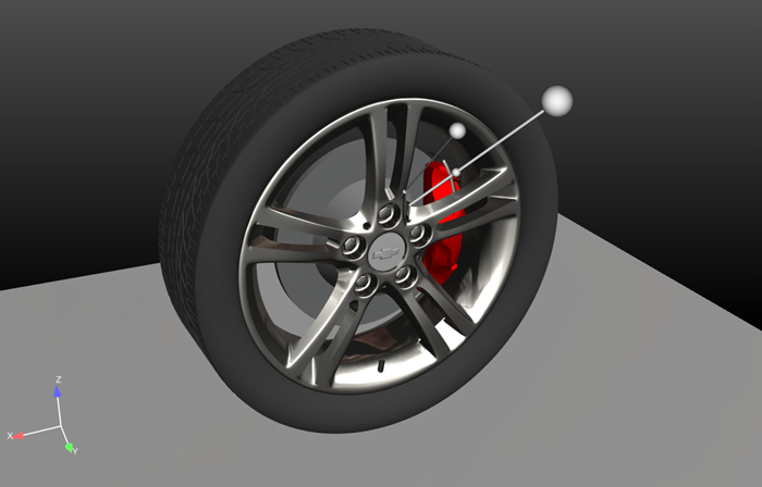
If we introduce two more directional light sources at locations and in the directions shown in this image:
And now ray trace the scene, we get the following image:
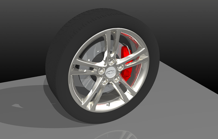
As you can see, we now have shadows, better reflections, and better lighting in the tread part of the tire. However, the chrome is also fully saturated in some areas of the wheel. We might consider using a less intense light for one or more of the lights to make this a better image.