


The following topics are included in this section:
- Viewport Areas on the Desktop
- Create a New Viewport
- Select Viewports
- Move and Resize Viewports
- Set Viewport Background Color or Image
- Set Viewport
- Display Selected Parts in Viewports
- Set Case Visibility Per Viewport
- Perform Transformations in Viewports
- Reset Viewport Transformations
- Setting/Changing Viewport Part Bounds
- Delete Viewports
- Other Notes

On startup, EnSight creates a single viewport that fills the Graphics Window. To create a new viewport:
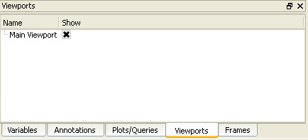
Click Viewports tab and select a viewport in the list panel to make Viewport Quick Action icons available. You can alternatively click in the background of one of the viewports.
Click the New Viewport icon.

OR
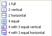
Click the Viewports Layout pull-down icon to select any of the standard viewport layouts.
Note: You can also right click in the viewport list and select .
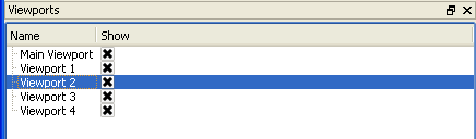
When you create a new viewport, it automatically becomes the currently selected viewport. Any action to change viewport always operates on the currently selected viewport(s). To select viewports:
Click Viewports tab and select the desired viewport(s) in the Viewports list panel. You can alternatively click in the background of the desired viewport.
Note: The typical multiple selection techniques can be used. Ctrl click to append additional viewports to the selection. Shift click to select a range of viewports.
Note: The selected viewport is also changed in other modes (such as View) any time you perform some action in a viewport (such as rotation). There is however, no visual feedback of this change unless or until you have the Viewport list visible.
Viewports can be easily moved and resized. You can either reposition a viewport with the mouse in the Graphics Window, or precisely by entering exact values. To move or resize a viewport:
Get the move and resize hotpoints to appear by clicking in the background or hovering the mouse over the border of the desired viewport.
To move a viewport, click and hold on the move hotpoint as you drag the viewport to the desired location.

To resize a viewport, click and hold on the resize hotpoint as you drag the corner to the desired location.

To precisely reposition a viewport:
Click the Selected viewport(s) position icon to open the Create/edit Viewports dialog. Alternatively you can double click (or right click and select Edit...) on the viewport in the list. Then open the Location Attributed area.

Enter new values in the Origin X,Y, Width, or Height fields (and press Return). You can alternatively use the sliders to change the Width and Height. The origin (at 0,0) is the lower left corner of the Graphics Window.
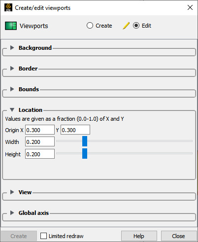
Note: The values are normalized to the width and height of the default viewport (i.e. the Graphics Window).
To quickly or to automatically arrange a number of viewports right-click on the viewport and choose Viewports → Manually arrange which will prompt you to create a single large viewport and a grid arrangement of the remaining viewports.
Right click and choose Viewports → Auto arrange to have your viewports quickly automatically arranged in a pre-defined fashion.
EnSight permits overlapping viewports. You can control the ordering (from front to back):
Click the Pop viewport(s) forward icon to bring the selected viewports to the top.

Click the Push viewport(s) back icon to send the selected viewports to the bottom.

Note: Viewport 0 is always displayed first, therefore it cannot be pushed or popped with these icons
The global axis display in the viewport can be controlled through the Global axis turndown:
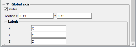
Here, the location of the global axis display in the viewport is given in X [0-1] and Y[0-1] location in the viewport.
Additionally, with the Labels section, you can control what labels are shown for each of the nominal XYZ directions. A limit of 4 characters are allowed for this label.
Viewport background colors can be constant, blended, or inherited from the default viewport. To set viewport background color:
Click Viewports tab and select a viewport in the list to bring up the Viewport Quick Action icons.
You can alternatively click in the background of one of the viewports.
Select the desired viewport(s) by any of the methods described above.
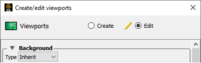
Click the Selected viewport(s) background color icon to open the Create/edit Viewports dialog, in the Background section.

The Type pull-down controls the type of background coloring used. There are four types: Blended, Image, Single color and Inherit.
Single color
A single color will be used for the entire background. To set a single color:
Select Single color from the Type pull-down.
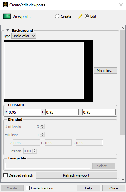
Either enter values in the RGB color fields (and press return
OR
Click the Mix color... button to open the Color Selector dialog, see Use the Color Selector.
The viewport should be refreshed automatically, but if not you can click .
Blended
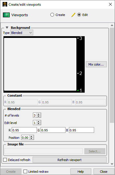
Up to 5 horizontal level colors can be specified with interpolation between levels. To set a blended background:
Select Blended from the Type pull-down.
Enter the desired number of levels in the # of Levels field (and press Return). Up to five levels are supported.
To edit a color, first select it by clicking on the number label in the Viewport Color window.
As shown, level 1 is currently selected. Alternately, you can enter a value in the Edit Level field or click the up/down arrows.
Change the selected color by either entering new values in the RGB fields (and pressing Return) or clicking the button to open the Color Selector dialog.
You can also change the relative vertical position of a level by either clicking on the level number with the left mouse button and dragging up or down
OR
By entering a new value in the Position field (and pressing Return).
Click , if needed.
Inherit
The selected viewports inherit the background type and color from the default viewport. To set an inherited background:
Select Inherit from the Type pull-down.
Click , if needed.
Image
The image specified will be used as the background for the selected viewports. To set an image background:
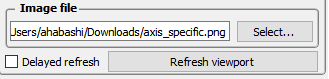
Select Image from the Type pull-down.
Enter the filename for the background image to use or click the button and navigate to it.
Note: The image must be a format that is recognized, but most common image formats are.
Click , if needed.
Viewports can be displayed with a variety of options:
Click Viewports tab and select a viewport in the list to bring up the Viewport Quick Action icons. You can alternatively click in the background of one of the viewports.
Select the desired viewport(s) by any of the methods described above.
Set the desired attribute as described below:
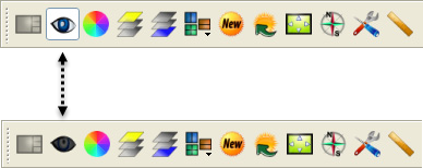
Click the Selected viewport(s) visibility icon to toggle display of the selected viewports on or off.
Click the Selected viewport(s) border icon to open the Border section of the Create/edit Viewports dialog.

Click the toggle to display a border.
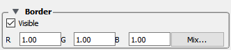
Enter values in the RGB fields (and press Return) or click the button to open a Color Selector dialog, see Use the Color Selector.
Click the Select viewport(s) special icon to open the View section of the Create/edit Viewports dialog.

Each viewport has its own toggles for perspective, hidden surface, and hidden line drawing styles. These controls will toggle the respective attribute for the selected viewports. See Set Drawing Mode and/or Set Global Viewing Parameters for more information.
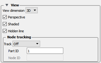
In addition, a viewport can be 3D or 2D in nature. If the viewport is designated as 2D, only planar parts may be displayed in the viewport and transformations will become 2D limited.
A viewport can be set such that it will track a node number, a part centroid, or one of the part min or max values. Therefore as a model changes in time, the viewport will stay centered on that location. See Do Viewport Tracking for more information.
See Set Drawing Mode, Set Global Viewing Parameters and Do Viewport Tracking.
Part visibility can be a set on a per-viewport basis such that some parts are visible in some viewports but not in others. To set part visibility per viewport:
Select the desired part(s) in the main Parts list.
Click the Visibility per viewport icon. The Part Viewport Visibility dialog displays a schematic of the current viewports. The part is currently visible in the green viewports but invisible in the black viewports.

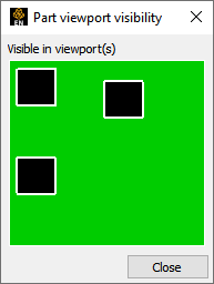
Click in a green viewport to disable display of the selected part(s) in that viewport
OR
Click in a black viewport to enable display of the selected part(s) in that viewport.
Note: A similar interface for setting this attribute appears in the General section of the Create/edit Parts dialog.
If you have multiple cases in your session of EnSight, you can set viewport visibility for all parts associated with a case. This makes it easy to display one case per viewport. To set case visibility per viewport:
Select the desired case from the Case menu ( → ).
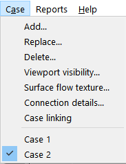
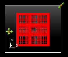
Select → to open the Case visible in viewport(s)? dialog.
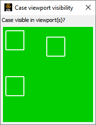
Click in a green viewport to disable display of the selected case in that viewport
OR
Click in a red viewport to enable display of the case in that viewport.
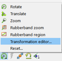
You can transform objects in a user-created viewport as easily as in the default viewport (See Rotate, Zoom, Translate, Scale for details). For precise viewport transformations, you can use the Transformations Editor on a per viewport basis:
Click the Graphics window transforms icon, then select
To perform precise transformations in a viewport, click the desired viewport in the Which viewport(s) window and perform the transformation.
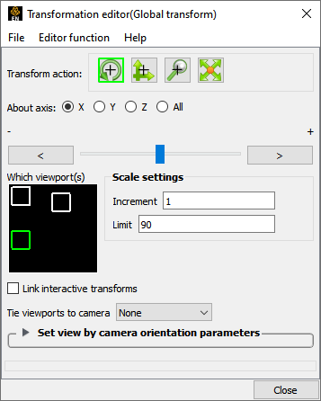
To select more than one viewport, simultaneously hold down the Ctrl key and click on additional viewports.
Note: This action will change the currently selected viewport(s).
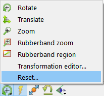
The transformations for one or more viewports can be reset at any time in the Reset Tools and Viewport(s) dialog.
Click the Graphics window transforms icon, then select
Select the viewport(s) on which the reset will act.
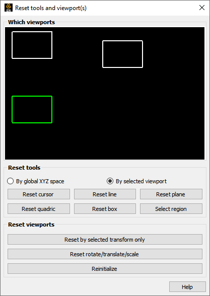
Click on the appropriate button to perform the reset action desired.
You can reset the selected action only, all rotates translates and scales at once, or do a complete reinitialization of the viewport.
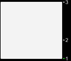
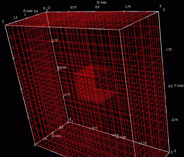
Part bounds can be displayed within a viewport. This is useful for understanding the size of the model domain.
To turn on part bounds globally, toggle the Bounds visibility under the menu.
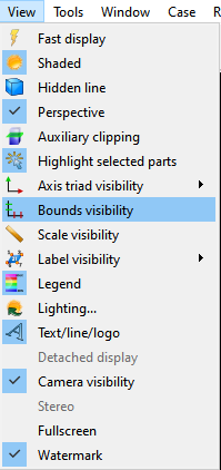
This will display the bounds around the parts in the viewports.
To control the of these bounds, click the Selected viewport(s) part bounds icon. Which will open the Bounds section of the Viewports Feature Panel.

Select General or the Axis specific tabs.
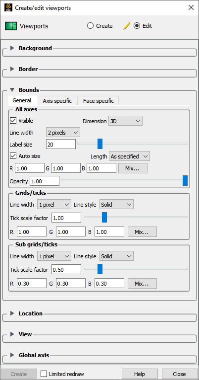
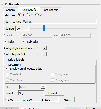
Modify any desired.
Including the visibility toggle if you don’t desire to see the bounds in the selected viewports.
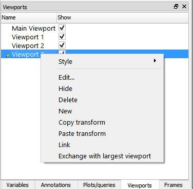
A created viewport can be deleted at any time:
Right click on the desired viewport in the Viewports list panel and select .
OR
if multiple desired:
Select the desired viewports in the list by any of the typical methods. (Hold down the Ctrl key to select multiple viewports)
Right click on the selection and choose .
Border visibility and color, and lighting for the viewports can also be controlled in the Create/edit Viewports dialog.
You can interactively transform multiple viewports simultaneously by selecting the viewports you want to link together and turning on the Link Interactive Transforms toggle in the Transformation Editor dialog. Those viewports that are highlighted in green will now transform together for any transformations performed in the Transformation dialog. Linking does not apply to transformations performed by the mouse in the graphics window.
You can copy the transformations from one viewport to another. First select the viewport you wish to copy, then select Editor Function → Copy Transformation State. Next select the viewport(s) you wish to modify and select Editor Function → Paste Transformation State.