


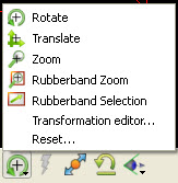
The Graphics window transforms icon on the Tools Icon Bar controls the operation of the left mouse button (by default) in the Graphics Window:
Fit the geometry to the viewport

To Rotate
Click the Rotate icon.
Move the mouse pointer into the Graphics Window.
Click and hold the left mouse button and:
move the mouse left and right to rotate about the screen Y (vertical) axis, or
move the mouse up and down to rotate about the screen X (horizontal) axis, or
hold down Ctrl and move the mouse left and right to rotate about the screen Z axis.
Move the mouse over the axis triad in the graphics area. Hot points will display on the end of the triad axis. If the viewport is 3D, then click the view you wish to show, that is, the hot point on the X axis will move the model such that you are looking form the +X axis towards the origin. If you want to view from the -X axis, hold Ctrl when you click on the X axis. If the viewport is 2D, then clicking on any hot point will flip the direction you are looking the viewport from.
Press the F1, F2 or F3 keys for 45 degree rotation about the X, Y, or Z axis, respectively. Hold Ctrl down for -45 degree rotation. (Note: cursor must be in the EnSight window for F keys to work)
To put the geometry in free rotation mode, Put the cursor in the EnSight graphics window. Press the F4 key, and left click in the graphics window and drag the mouse to set the view in motion and then let the left mouse button up. The geometry will continue to freely rotate according to the speed of your drag. Press F4 to stop the free rotation.
To Translate
Click the Translate icon (or use the middle mouse button in steps 2 and 3 (default)).
Move the mouse pointer into the Graphics Window.
Click and hold the left mouse button and:
move the mouse left and right to translate in the screen X (horizontal) direction, or
move the mouse up and down to translate about the screen Y (vertical) direction, or
hold down Ctrl and move the mouse left and right to translate in the screen Z direction.
Note: You can open the Transformation Editor dialog and the Reset Tools and Viewports dialog here as well.
To Zoom
Click the Zoom icon (or use the middle mouse button in steps 2 through 5 (default)).
Move the mouse pointer into the Graphics Window.
Click and hold the left mouse button.
Drag down to zoom in or drag up to zoom out.
Hold down Ctrl and move the mouse to pan.
To Rubber-Band Zoom
Click the Rubberband Zoom icon.
Move the mouse pointer into the Graphics Window and position it at one corner of the desired viewing region.
Click and hold the left mouse button.
Drag to include the desired viewing region. An outline of the region will appear as you drag.
To Rubber-Band Zoom Using the Selection Tool
Click the Selection Tool Rubber-band Positioning icon.
Move the mouse pointer into the Graphics Window and position it approximately at one corner of the desired viewing region.
Click and hold the left mouse button.
Drag to include the desired viewing region. An outline of the region will appear as you drag.
Manipulate the tool as desired, by clicking at the center and dragging to a new position or clicking on any corner and resizing.
Note: The aspect ratio will be preserved as indicated by the dotted lines within the tool.
Click the zoom (magnifying glass) indicator at the top left of the tool.
The Graphics window view orientation icon can be used to quickly view the scene from the global axes directions.
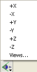
Press +X to view the scene from the positive X axis (looking toward the origin). The +Y, +Z, -X, -Y, -Z buttons are similar.
It also provides quick access to the Views Manager that will allow you to save and restore your own custom views.
Note: You also have the + and - axes buttons available in the Views Manager.
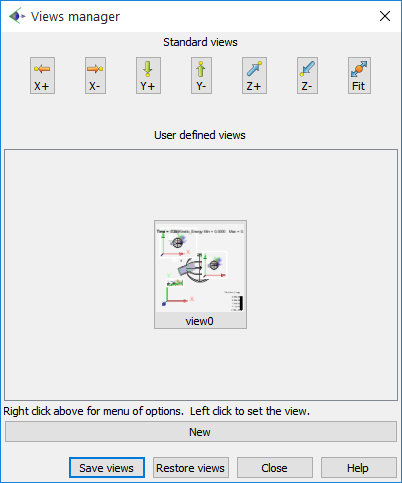
To save your own custom views:
Orient the scene as desired.
Click the button. And the view will be shown.
Repeat steps 1. and 2. until you have all the views you desire.
Click the button, and specify the folder in the dialog that comes up. This will save all of the views you defined.
To restore your custom views:
Click the button, and specify the folder containing your views. This will restore them to the dialog. To apply any views in the dialog, simply left click on them.
Note: Zooming actually changes the location of EnSight's virtual camera or look-from point. Zooming in moves the camera closer to the object; zooming out moves it farther away. The look-from/look-at points (Set LookFrom / LookAt) can also be edited explicitly.
If you have multiple viewports visible (Define and Change Viewports), each one can be manipulated independently. To transform in a different viewport, place the mouse pointer within the bounds of that viewport before you click the left mouse button.
You can reset transformation parameters (as well as tool and frame transforms) by clicking Reset.... See Reset Tools and Viewports for more information.
The button is useful in causing the currently visible parts to be centered and zoomed to fit within the selected viewport.