


The part visual representation (part element settings) controls how you see the elements that you have loaded on the server in the graphics window on the client. To be clear, the full part and all the elements are loaded and maintained on the server, but the part visual representation exists on the client. For example, you can make a clip plane of a flow field that is set to non-visual because the clip happens on the server. Part element settings are per part, that is, the child clip can be shown in full representation, showing all elements, while the parent flow field is set to non-visual. The ability to change part representations is a powerful management tool in EnSight. This allows you to see the border elements, just an outline of the part, or to make the part entirely non visual. Not only can you select the visual representation that best meets your needs, you can also manage graphics memory and performance more effectively. Using simpler representations both reduces your client memory consumption as well as improves graphics display speed. EnSight provides six representation modes for parts (as well as three modes that are a combination of the six depending on the dimensional order of parts):
|
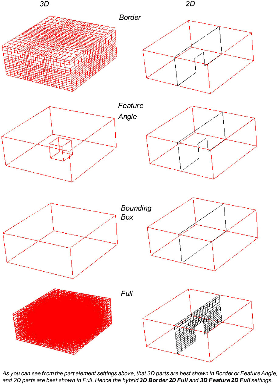
Full |
Every face and edge of every element is displayed. Warning: do not use this for a 3D part with a large number of elements because it moves every face of every element from the server to the client and can overwhelm your client memory and your graphics card's ability to process the data. Conversely, this is often a useful choice for 2D parts. |
|
Border |
Displays the outside surface of your part. Only unshared faces (for 3D parts) or unshared edges (for 2D parts) are displayed. This is often a useful choice for 3D parts. |
|
Feature Angle |
Only those edges joining faces in the Border representation for which the angle between the faces is less than some threshold are displayed. Feature Angle typically extracts the topological features of interest in a model. This is often a useful choice for 3D parts. |
|
Non Visual |
No visual representation exists on the client. Note: This is different than just turning off the visibility. Choosing this option means that NO 2D surface elements are moved to the client for this part and no client memory is allocated for the part. Turning off the visibility simply makes the existing polygons in client memory invisible. It is often useful to use Non Visual as the representation for 3D CFD flow field parts to save memory - especially if you also have shell border part(s) to display the outer surface. |
|
3D Border, 2D Full |
Display 3D parts in Border representation; display 2D parts in Full representation. This is useful in a structural model to show the outside border of a 3D object, and to show all the elements of the shell border parts. |
|
3D Feature, 2D Full |
Display 3D parts in Feature representation; display 2D parts in Full representation. This is useful for a CFD model to show the outside features of the 3D flow field and to show all the elements of the 2D border parts such as inlet, and wall and boundary condition part(s). |
|
3D nonvisual, 2D Full |
Display 3D parts in Non Visual representation; display 2D parts in Full representation. This is useful for a CFD model to avoid loading any of the element surfaces of a high-resolution 3D flow field (to preserve client graphics memory and performance) and to still show all the elements of the 2D border parts such as inlet, and wall and boundary part(s). |
|
Bounding Box |
Only a wireframe box representing the XYZ extents is displayed. |
|
Volume |
Every element is displayed with a controllable level of transparency. Use this with caution as this can require a large amount of client memory on your hardware graphics card: for unstructured rendering, 100MB/ million Tets, and structured rendering 2bytes/cell + 72 bytes / pixel. |
Additionally, one can specify the use of only a point and normal (instead of the element connectivity) for the specified part representation to be loaded. This reduces the number of entities to visualize and therefore, is most useful for very dense models. Double click on the part, and choose advanced, and under the node, element and line turndown, turn on the Load points and normals only toggle.
The site wide default visual representation (as well as extension mapping) is individually specified for data formats in the $CEI/ensight242/site_preferences/ensight_reader_extension.map file. For example .case files always open with the EnSight Case gold reader and parts are always in 3D Feature, 2D Full mode. Custom visual representation can be specified in the user's local ensight_reader_extension.map file located in the users local EnSight Defaults directory.