


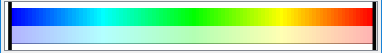
The default color palette created for each variable has five Levels (with the minimum and maximum set to the range of the variable at the time step selected when the variable was activated). The color ramp is a standard spectrum with the five Levels set to (from min to max) blue, cyan, green, yellow, and red.
Active scalars and vectors have color palettes that are initialized to the variable range for the currently loaded parts.
An active variable has a solid color in the Variables List Panel while an inactive variable (not yet read by EnSight) is grayed out. To activate an inactive variable you can right click on the item in the list and Activate it.
EnSight can display multiple color legends in the Graphics Window:
Click the Annotation tab and open the Legend group.
Select the desired variable(s) or variable components in the list.
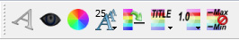
Turn on visibility via the Quick Action Icon Bar.
To remove a legend repeat the procedure or you can remove the legend by right clicking and performing a operation.
Color legends have a number of display attributes including size, position, and how/where the variable labels are formatted. See Create Color Legends for details.
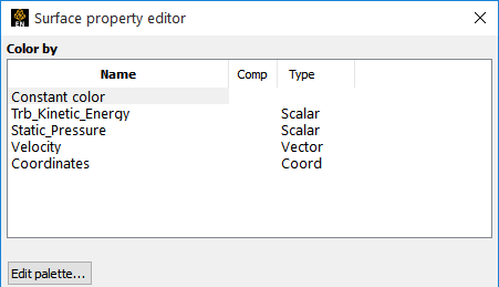
The Palette Editor provides access to all aspects of variables including min/max information, histogram, and variable value mapping to color and transparency:
Select the part you want to edit, then click the Color icon in the Quick Action Icon Bar to open the Color Editor.
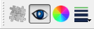
Click the button to bring up the Palette Editor.
Note: Notice that if you have chosen to color by a variable (here Density)
Select the palette to be edited from the Palette for variable pulldown.
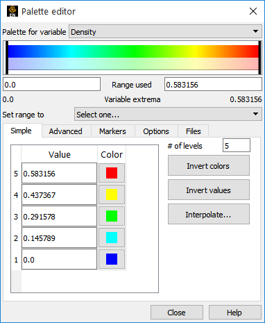
Grab the Minimum/Maximum Palette Value Slider.
Range used allows you to type in a Minimum/Maximum Palette Value.
The Simple tab opens by default in Simple Tab Palette Levels (and variable values). Enter a new value if desired. Click on the Color to change.
Update variable range using Set range to
extrema
selected part(s)
Note: Element representation of part(s) matters.
currently visible part(s) in selected viewport.
# of levels allows you to enter a desired number of Levels in the palette (2 to 21).
Invert colors reverses colors/levels.
Interpolate... lets you interpolate between two levels. Enter the upper and lower levels and click interpolate to create the intermediate levels.
To change the colors associated with the levels
Click on the Color for the level you wish to modify and select a new color in the pop up dialog.
OR
Click the button to invert the color order, or Invert values to invert the values order.
OR
Click on the Tab and choose a new palette and click to load a new palette.