


EnSight is a powerful software package for the postprocessing, visualization, and animation of complex datasets. Although EnSight is designed primarily for use with the results of computational analyses, it can also be used for other types of data.
This document provides a very brief overview of EnSight. Consult Overview in the Ansys EnSight User Manual for additional overview information. This article is divided into the following sections:
The graphical user interface (GUI) of EnSight contains the following major components:
Note: This whole upper level of the graphical user interface is referred to as the Desktop.
- Quick Action Icon Bar

- Main Menu

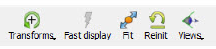
- Feature Icon Bar
Sets the current feature and opens the Feature Panel.

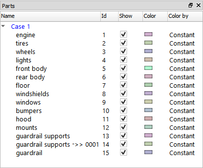
- Parts List
All parts from your model as well as created parts (for example, clips, isosurfaces) are listed here. Click an item to select part(s) to operate on.
- Messages Area

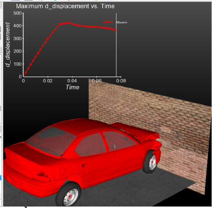
- Graphics Window Showing Inset Plot and Viewport
- Information Button
Click to see information dialog.

- Transformation Control Area
Buttons that control the current transformation operation (for example, rotate or translate) associated with mouse action in the Graphics Window.
Overview in the Ansys EnSight User Manual provides additional overview information on the user interface.
To facilitate the handling of large datasets and efficiently use networked resources, EnSight was designed to distribute the postprocessing workload. Data I/O and all compute intensive functions are performed by a server process. The server transmits 3D geometry (and other information) to a client running on a graphics workstation. The client handles all user interface interaction and graphic rendering using the workstation's built-in graphics hardware.
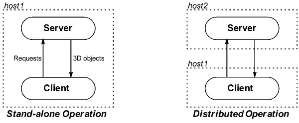
The client and server each run as separate processes on one or more computers. When distributed between a compute server and a graphics workstation, EnSight leverages the strengths of both machines. When both tasks reside on the same machine, a stand-alone capability is achieved. The client-server architecture allows EnSight to be used effectively, even on systems widely separated geographically.
Before EnSight can be used, the client and server must be connected. For standalone operation, you
simply run the ensight script and the client and server are started and
connected for you. For distributed operation (as well as for standalone operation when more
control is desired), there are two methods of achieving a connection: a manual connection
(described in the Getting Started manual) or an automatic connection (described in Connect EnSight Client & Server).
EnSight's cases feature allows you to post-process multiple datasets simultaneously. Cases is implemented by having a single client connected to multiple servers running on the same or different machines.
One of the central concepts of EnSight is that of the part. A part is a named collection of elements (or cells) and associated nodes. The nodes and/or elements may have zero or more variables (such as pressure or stress). All components of a part share the same set of attributes (such as color or line width).
Parts are either built during the loading process (based on your computational mesh and associated surfaces) or created during an EnSight session. Parts created during loading are called model parts.
All other parts are created during an EnSight session and are called created or derived parts. Created parts are built using one or more other parts as the parent parts. The created parts are said to depend on the parent parts. If one or more of the parent parts change, all parts depending on those parent parts are automatically recalculated and redisplayed to reflect the change. As an example, consider the following case. A clipping plane is created through some 3D computational domain and a contour is created on the clipping plane. The contour's parent is the clipping plane, and the clipping plane's parent is the 3D domain. If the 3D domain is changed (for example, the time step changes), the clipping plane will first be recalculated, followed by the contour. In this way, part coherence is maintained.
Since operating on parts is integral to the operations you will perform in EnSight, it is important that you are aware of the different ways this can be done. See Select Parts.
See the Introduction to Part Creation for more information on parts.
Documentation for EnSight is available online. See Use the Online Documentation for more information as well as hyperlinks to the main documents. Online documentation is accessed from the Main Help menu in the user interface. In addition, major dialog windows contain buttons that will open a relevant How To article.