In this demonstration, we will load a simple CFD model of the viscid, subsonic symmetric flow around a half-model of the shuttle orbiter. The dataset consists of the standard X (mesh) and q (results) PLOT3D format files.
Start EnSight as described in Starting EnSight and cancel the Welcome Screen.
Select → from the Main EnSight menu.
This opens the File Selection dialog.
Navigate to the $CEI/ensight242/data/plot3d directory.
Click shuttle.xyz in the Files list.
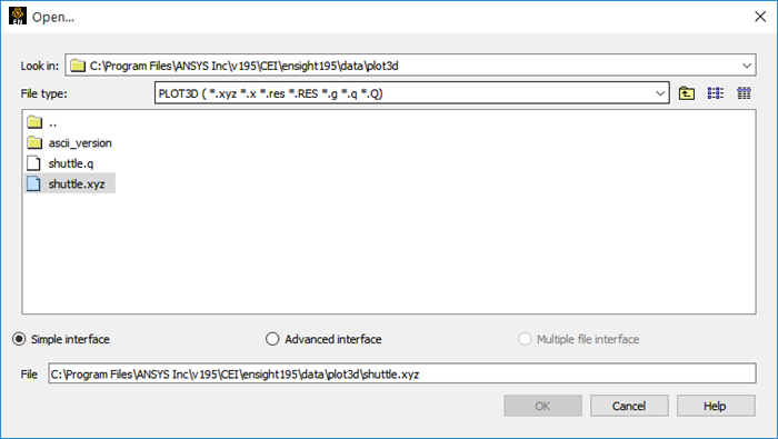
Click Select parts to load... to accept the selections that appear in the File and results fields and to close the dialog window.
When the File Selection dialog is closed, EnSight reads the indicated file but does not load any of the geometry.
A number of different PLOT3D formats are supported by EnSight. For a complete description, see How To Read Data (Help → How to manual...) or PLOT3D Reader ( Help → User manual...). EnSight scans the PLOT3D files to determine which format is being used.
After the file has been read, you might not see any loadable parts. If this is the case, then right-click the Name column and choose Display loadable parts → On.
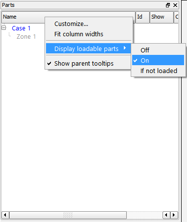
Now, the Parts list will show Zone 1 as a grayed out entry in the list indicating that the zone is available but not currently loaded.
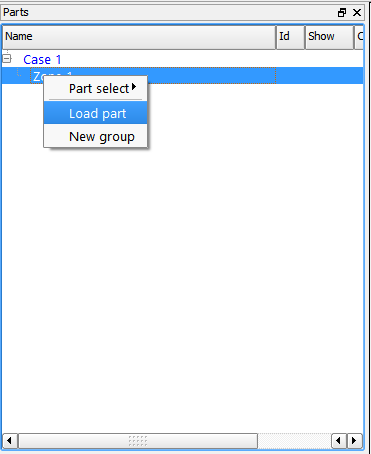
Right-click Zone 1 in the Parts list and select Load Part from the pulldown to bring up the Structured Part Builder dialog.
This dialog allows us to create parts from a structured block. We can extract out any range of I, J, K from the block and we can extract out multiple parts from the same block.
The most basic part is the fluid flow region, in this case 8-noded hexahedral cells surrounding the surface of the shuttle geometry. For reference, this single block will be named by typing in a Part Description before creating the part. A second part, defined by the surface of the geometry, will be created by choosing an appropriate limited range of nodes (which are normally known by the author of the PLOT3D mesh). In this manner any number of surface parts may be created in addition to the 3D (fluid) parts. Note that the Data Part Loader may be used at any time to create new parts from the original PLOT3D data files.
Click Element Visual Rep. and change the setting to Feature Angle.
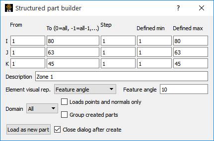
Type
external flow fieldin the Description field.Uncheck the button - this will allow us to create two parts from this block.
Click button.
At this point the external flow field part will show up in the Parts list. The graphics window will not display the new part until the dialog is closed.
Change I indices to
1-54, the J indices to1-53and change the K indices to 1-1 (the geometry's surface).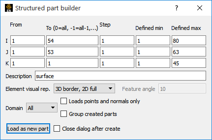
Click Element Visual Rep. and change the setting to 3D border, 2D full.
Type
surfacein the Description field.Click Load as new part.
Click X to Close.
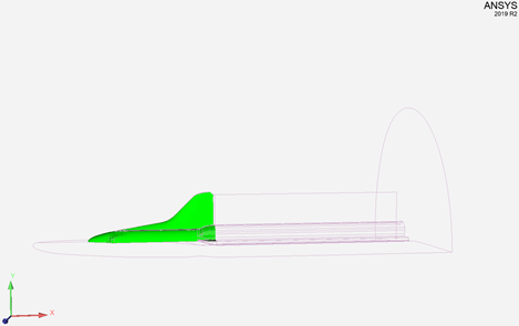
The second part now appears in the Parts list and both parts will appear in the graphics window. The external flow field is displayed as a wire frame and the surface is displayed as a mesh. As the flow field and geometry are both symmetric, only a half-model was used. The image in your Graphics window should appear as follows: