


The major components of the EnSight user interface are shown below.
Note: This whole upper level of the graphical user interface is referred to as the Desktop.
Quick Action Icon Bar
Shows attributes and functions for the last object selected - in this case part attributes.

Tools Icon Bar
Contains Tools and Transformation control access (this may appear at the bottom).
Main Menu

Feature Icon Bar

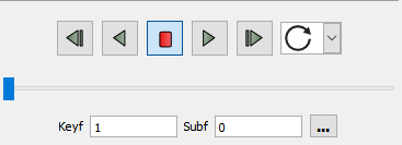
Transient Controls
Parts list
Main Menu
The Main menu provides access to basic EnSight functionality. The Help menu (at the far right end of the menu bar) contains items for accessing online help.
Message/Feedback Area
The Message area displays brief messages during various operations.
Information Button
Clicking the button  in the Tools Icon Bar will bring up the EnSight
Message Window where additional information about EnSight operations
is displayed. The color of the button will indicate when
content is present
in the Tools Icon Bar will bring up the EnSight
Message Window where additional information about EnSight operations
is displayed. The color of the button will indicate when
content is present  .
.
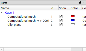
Parts List
The Parts list displays all parts associated with the current session. A part is a named collection of elements (or cells) and associated nodes. All components of a part share the same set of attributes (such as color or line width).
Parts are accessed via the Parts list. Items in the list are selected by placing the mouse pointer over the item and clicking the left mouse button. You can extend a selection by pressing Shift as you click an item. Additional techniques for selecting parts are discussed in User Interface Conventions.
Understanding part concepts is crucial for productive use of EnSight. See Parts and Part Attributes for more information on parts.
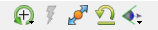
Feature Icon Bar
The Feature Icon Bar contains icons associated with the major features of EnSight (not all of which will be showing by default). Clicking the left mouse button on an icon selects the feature and opens the associated interface in the Feature Panel.
Attached to the Feature Icon Bar are the secondary features. By default contours, isosurfaces, clips, vector arrows, and particle traces. These icons are simply fast access to the Features, that is, if you click on the Clip icon it sets the Part feature into the clip setting.
All of the features (and secondary features) on the Feature Icon Bar can be customized. Simply right-click on the Feature Icon Bar and select Customize Feature Toolbar...
Features include the following:
|
Part Icon |
 |
Opens the Parts Feature Panel which allows editing and creation of parts. |
|
Variable Calculator |
 |
Opens the variable calculator, for creating computed variables. |
|
Query/Plot |
 |
Opens the Query/plot Feature Panel allowing editing and creation of queries and plotters. |
|
Interactive Query |
 |
Provides controls for specifying interactive queries, which display variable values as the mouse is moved over objects in the Graphics Window, as the cursor tool is moved within a volume, or at specific node, element, ijk, or xyz locations. |
|
Viewports |
 |
Opens the Viewports Feature Panel and allows the editing and creation of viewports. |
|
Annotations |
 |
Opens the Annotation Feature Panel and allows the editing and creation of various annotations such as text, lines, dials, etc. |
|
Solution Time |
 |
Provides controls for managing time for transient datasets. Note: This icon is only present for transient data. |
|
Flipbook Animation |
 |
Provides controls for specifying Flipbook animations. Flipbook animations are on-screen animations that permit graphic transformations during playback. Flipbooks can be used to animate clipping planes and isosurfaces and are also useful for visualizing transient data |
|
Keyframe Animation |
 |
Provides controls for specifying keyframe animations. Keyframe animation provides sophisticated motion control and output options for generating animations for either online presentation (for example, mpeg) or video. |
|
User Defined Tools |
 |
Provides a user interface to plug-in extensions from Ansys and site or user customization. |
|
Contour |
 |
Create or modify a new contour (isoline) part using the part(s) selected in the Parts list as parents and the specified variable. |
|
Isosurface |
 |
Create or modify a new isosurface part using the part(s) selected in the Parts list as parents and based on an isovalue of the variable specified. |
|
Clip |
 |
Create or modify a new clip part using the part(s) selected in the Parts list as parents. EnSight can create several types of clips including 1D line clips, planar clips, and quadric clips. |
|
Vector Arrows |
 |
Create or modify a new vector arrow part using the part(s) selected in the Parts list as parents and the variable specified. Vector arrows display direction and magnitude of a vector variable. |
|
Particle Trace |
 |
Create or modify a new particle trace part using the part(s) selected in the Parts list as parents and the variable specified as the velocity variable. |
Other Secondary Features not shown in the typical start graphical user interface (Use right-click to Customize the Feature Icon Bar to add these)
|
Subset Parts |
 |
Create or modify a new subset part from node and/or element label ranges of model parts. |
|
Profile Plot |
 |
Create or modify a new profile plot part using the part(s) selected in the Parts list as parents and the variable specified. A profile plot is the 1D counterpart of an elevated surface. |
|
Elevated Surface |
 |
Create or modify a new elevated surface part using the part(s) selected in the Parts list as parents and the variable specified. An elevated surface is a surface projected away from another surface with scaling based on the value of a variable. |
|
Vortex Cores |
 |
Create or modify a vortex core part using the part(s) selected in the Parts list as parents and the variable specified. |
|
Shock Surfaces/ Regions |
 |
Create or modify a shock surface or region part using the part(s) selected in the Parts list as parents and the variable specified. |
|
Separation/ Attachment Lines |
 |
Create or modify separation or attachment line parts using the part(s) selected in the Parts list as parents and the variable specified. |
|
Material Part |
 |
Create or modify parts which are based on the intersection or domain of elements with mixed material values. |
|
Tensor Glyph |
 |
Create or modify a tensor glyph part using the part(s) selected in the Parts list (as parents) and the tensor specified. This icon is invisible by default. |
|
Developed Surface |
 |
Create or modify a new developed surface part using the part(s) selected in the Parts list as parents. A developed surface is constructed by unrolling a quadric clip about its axis of revolution. |
|
Point Part |
 |
Create or modify a point part from specified locations in a parent part selected in the Parts list. A point part consists only of points and their variable values from the parent part. Think of a point part as a point clip. |
|
Extrusion Part |
 |
Create or modify a new extrusion part using the part(s) selected in the Parts list as parents. An extrusion part is the 3D part created from rotating or translating a 2D parent part and incrementally creating 3D elements from the 2D parent. |
Feature Panel
The Feature Panel provides the interface controls associated with the current feature selected from the Feature Icon Bar.
The Feature Panels provide buttons. Clicking the button will build a new object (such as an isosurface, clipping plane, or text annotation) based on current settings. Once built, the new object will appear in one of the object list panels (part, annotation, viewports, etc.).
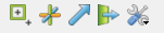
Quick Action Icon Bar
The Quick Action Icon Bar displays the icons associated with the most recently selected object (such as part, annotation, viewport, etc.). The icons displayed will depend on what object is selected. By default the Quick Action Icon Bar is displayed on the same level as the Feature Icon Bar but you are free to move it wherever you want by grabbing it by the tear off marker and dragging it to a new location. The Quick Icon Reference in the Ansys EnSight How-To Manual online documentation provides a quick reference for all EnSight icons as well as hotlinks from the icons to relevant online articles.
Transformation Control Area of Tools Icon Bar
The Transformation Control Area provides icons that control various aspects of object transformations. Transformations are accomplished by selecting the action (such as rotate), moving the mouse into the Graphics Window, clicking and holding the left mouse button, and dragging the mouse to achieve the desired transformation. Also keep in mind that rotate, translate and zoom are by default attached to the left, middle, and right mouse buttons.
Several transforms are found in the transformations pulldown (which effectively maps the transform to the mouse key (by default left) attached to the current transform.
Note: On MacOS, scrolling using the mouse wheel performs a transform. On Windows/Linux, the same behavior will perform a transform.
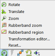
The possible actions are:
|
Rotate |
 |
Rotate: click and drag
|
|
Translate |
 |
Translate: click and drag
|
|
Zoom |
 |
Zoom: click and drag
Zoom is implemented by moving the look from point. |
|
Band Zoom |
 |
Rubber-band zoom: click and hold the left mouse button on one corner of the desired viewing region, drag to opposite corner. An outline of the region will appear as you drag. Release the mouse button to zoom to the outlined region. |
|
Rubberband region |
 |
Selection tool: click and hold the left mouse button on one corner of the desired viewing region, drag to opposite corner. An outline of the region will appear as you drag. Release the mouse button to see the selection tool. Adjust the center or corner locations of the tool further if needed. Then click the magnifying glass symbol near upper left corner to zoom. Or click the eraser symbol to blank out elements under the tool. |
|
Transformation Editor... |
Opens the Transformation Editor dialog. From within this editor, all global transforms (including scaling where appropriate) as well as frame and tool transforms can be controlled. There is also control of the center of transform, look-at/look-from locations, and z-clipping. |
|
|
Reset... |
Open the Reset Tools and Viewports dialog that permits easy resetting of all or some transformation operations. |
|
|
Reset Transforms |
 |
Resets the global transforms for the current viewport. |
|
Fit |
 |
Fits the currently visible model in the currently selected viewport and resets the center of transform to center of visible parts. |
|
Standard or Saved Views |
 |
A pulldown to set +/- X/Y/Z views or to bring up the views manager to store/recall saved views. |
|
Undo |
 |
Allows the user to undo/redo the last transformation. |
|
information |
 |
Read informational feedback for EnSight status |
Graphics Window
All 3D objects, as well as annotation entities, are displayed in the Graphics Window. The Graphics Window can contain additional (up to fifteen) user-defined viewports as well as X-Y plots.