Reviewing Fluid-Solid Interfaces
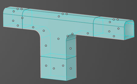
Discovery automatically detects and defines fluid-solid interfaces when you simulate heat transfer within and between fluids and solids. These fluid-solid interfaces can be reviewed by selecting the automatically created condition under Fluid-Solid Interfaces in the physics tree. Double-click the interface in the physics tree to load the Interface Review tool. Each interface pair is shown in the model as a single dot.
-
Select the interface pair you want to review.
The Interface Review tool allows you to review all interface pairs on selected primary bodies
 or primary faces
  . Narrow the review
further by selecting a secondary body to review only interface pairs between the
secondary body
. Narrow the review
further by selecting a secondary body to review only interface pairs between the
secondary body  and any primary body. You can also select a secondary face
 to review
only interface pairs between the secondary face and any primary face. You can also
ALT-select the secondary locations.
to review
only interface pairs between the secondary face and any primary face. You can also
ALT-select the secondary locations. -
(Optional) To exclude an interface from automatic detection, select the dot
representing the interface and click Exclude from interface
detection
 .
.
Excluded interfaces will be treated as insulated. If you wish to apply a different condition, you must apply conditions to both sides of the interface.
-
By default, interface faces are grouped by body. You can choose to group them by other
topologies, like tangent faces, or to apply no grouping so that interfaces are created on
all interface faces.
Here is an example of a model consisting of three bodies showing the different interface face groupings:
Option Description Group faces by body Four (4) interface pairs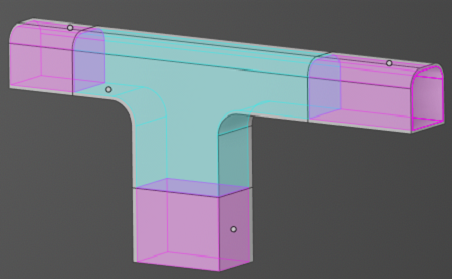
Group tangent faces Eleven (11) interface pairs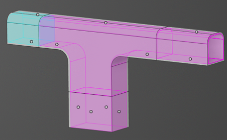
No grouping Twenty-seven (27) interface pairs