


Define regions as inlets and outlets when you expect one-way flow boundary conditions; define them as openings when you want to support simultaneous inflow and outflow over a single region. Care should be taken specifying velocity components for these boundary conditions as you are allowed to specify flow in either direction at an inlet or outlet.
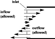
Inlets are used predominantly for regions where inflow is expected; however, inlets also support outflow as a result of velocity specified boundary conditions.
| Artificial walls for Inlets | |
|---|---|
|
Velocity specified condition
|
CFX-Solver allows both inflow and outflow, and therefore artificial walls are not erected when the specified velocity is out of the domain. |
|
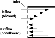
Pressure and mass flow condition
|
CFX-Solver enforces inflow by erecting artificial walls on those faces where the flow attempts to exit the domain. |
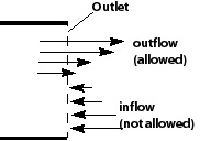
Outlets are used predominantly for regions where outflow is expected; however, outlets also support inflow as a result of velocity specified boundary conditions.
| Artificial walls for Outlets | |
|---|---|
|
Velocity specified condition
|
CFX-Solver allows both inflow and outflow; therefore artificial walls are not erected at outlets when the specified velocity is into the domain. |
|
Pressure and mass flow condition
|
CFX-Solver enforces outflow by erecting artificial walls on those faces where the flow attempts to enter the domain. |

Define a region as an "opening" when the full prescription of information at that location is not readily available; for example, if the value of pressure is known, but the direction of flow is unknown. It is also important to note how Ansys CFX treats the value of pressure that you specify at an opening. If, during the course of the solution, flow is directed out of the domain, then the value is treated as static pressure. If, instead, the flow is entering the domain, the value is taken to be total pressure, from which the static pressure is calculated.
A large number of flow simulations can make use of the Static
Pressure option to describe an outlet boundary where flow is out
of the domain, and the Total Pressure option to specify an
inlet boundary where flow is into the domain. As the solution progresses, inflow
may occur at an outlet boundary, or outflow at an inlet boundary, due to
either:
The behavior of the solver
A physical phenomenon, such as a recirculation zone, close to the boundary.
In either case, the CFX-Solver will try to enforce outflow by erecting artificial walls on the boundary mesh faces to prevent inflow occurring. If the full inlet/outlet is walled off and it was the only boundary condition that set the pressure level, then the artificial walls create a serious problem: temporarily, there is no pressure level felt by the code. This usually causes a linear solver failure. If you check the CFX-Solver Output file, a message like the following should be present:
+--------------------------------------------------------------------+
|                     ****** Notice ******                           |
|  A wall has been placed at portion(s) of an OUTLET                 |
|  boundary condition (at   31.4%  of the faces, 12.3% of the area)  |
|  to prevent fluid from flowing into the domain.                    |
|  The boundary condition name is: exit.                             |
|  The fluid name is: AirIdeal.                                      |
|  If this situation persists, consider switching                    |
|  to an Opening type boundary condition instead.                    |
+--------------------------------------------------------------------+
If you suspect that the problem is a numerical one, then you overcome this by temporarily replacing the inlet/outlet boundary condition with a pressure-specified opening. Artificial walls are not erected with the opening type boundary, as both inflow and outflow are allowed (although you may have to specify information that is used if the flow becomes locally inflow). Restart the solver, and once the solution is further converged, the original boundary condition can be restored.
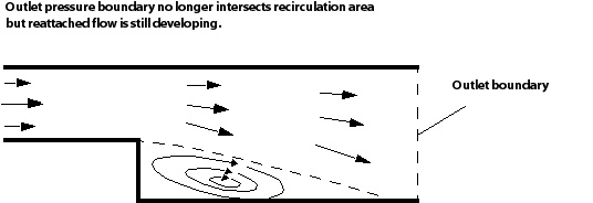
If you suspect that a real phenomenon is causing the inflow, for example, a recirculation region near an outlet, then two options are available to you:
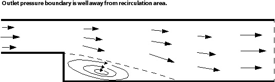
Move the outlet to a region well away from this influence by, perhaps, extending the flow domain further downstream. A good rule of thumb is to place the boundary a distance downstream that is at least 10 times the height of the last obstacle.
Alternatively, you may have reasons to want to maintain the location of that boundary, in which case, you can use an opening to describe subsonic flow where simultaneous inflow and outflow may occur. Generally, however, it should be noted that defining the boundary of your computational domain to cross a flow recirculation region is not a good idea. You are making a poor approximation of what is happening just outside the opening by not modeling it.
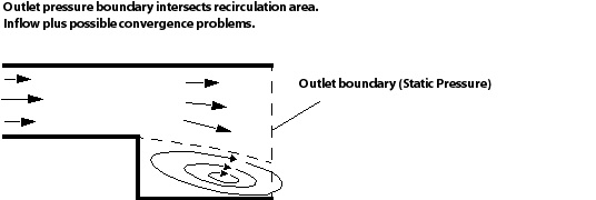
The diagram below, showing flow over a backward facing step, serves to illustrate the former approach. A recirculation region builds up downstream of the step as a result of the separated flow. An initial pressure boundary intersects this region with the result that flow re-enters the domain across it. Convergence problems will arise in this situation because the CFX-Solver will try to enforce an outward-flow-only condition, which is inconsistent with the physical nature of the flow. Although placing the boundary further downstream (beyond the re-attachment point) alleviates the inflow problem, the flow is still developing in the enlarged duct. A much better location would be at a point where the flow profile is not changing, well away from any zone of influence.
If, during the course of the solution, you do still experience convergence problems, the use of a small physical timestep may help to promote convergence.
When buoyancy is activated, the pressure calculated by the solver excludes the hydrostatic pressure gradient. This modified pressure is often called motion pressure because it is responsible for driving the flow. All boundary conditions are interpreted in terms of this modified pressure. For details, see Buoyancy and Pressure.
Furthermore, if there is a free surface flow at the boundary due to variations in density, temperature or height change; specifying a pressure profile at the boundary may be required.