


Using a mesh of adequate geometrical mesh quality is an important part of controlling discretization error. For details, see Discretization Errors in the CFX-Solver Theory Guide. It is also important for avoiding round-off errors during, for example, the solution of the linear equations that are produced by the discretization process. Significant measures of mesh quality may be broadly categorized as measures of mesh orthogonality, expansion and aspect ratio (or stretching).
Various forms of these measures are presented during different stages of the simulation process (for example, mesh generation, physics preprocessing, solution, and so on). It is important to realize, however, that the most relevant form of the orthogonality, expansion and aspect ratio measures is intimately related to the discrete approximations employed by the field solver being used. Moreover, acceptable ranges for the values of these measures also depend heavily upon the discretizations used.
The discussion that follows focuses on the measures that are most relevant to the CFX-Solver. The relationship between these measures and some of the values that are available in mesh generators or physics preprocessors or postprocessors is also noted.
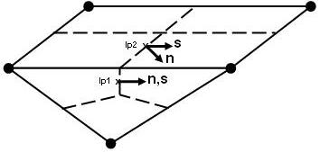
The concept of mesh orthogonality relates to how close the angles between adjacent element faces or adjacent element edges are to some optimal angle (for example, 90º for quadrilateral faced elements and 60º for triangular faces elements). The most relevant measure of mesh orthogonality for the CFX-Solver is illustrated below. It involves the angle between the vector that joins two mesh (or control volume) nodes (s) and the normal vector for each integration point surface (n) associated with that edge. Significant orthogonality and non-orthogonality are illustrated at ip1 and ip2, respectively.
The orthogonality angle, three related measures, and acceptable ranges are tabulated below with other measures that are available through the CFD-Post postprocessor and Ansys ICEM CFD meshing tools. Values outside of the suggested acceptable range will increase both sources and the amplification of discretization error. Poor convergence and divergence can be expected under these conditions.
|
Orthogonality Measure |
Acceptable Range |
Description and Notes |
|---|---|---|
|
Orthogonality Angle |
> 20° |
Area weighted average of
|
|
Orthogonality Factor |
> |
Area weighted average of all integration point surface scalar products of unit n and s vectors (that is, n·s) associated with each control volume
|
|
Orthogonality Angle Minimum |
> 10° |
Minimum of
|
|
Orthogonality Factor Minimum |
> |
Minimum of all integration point surface scalar products of unit n and s vectors (that is, n·s) associated with each control volume
|
|
Minimum/ Maximum Face Angle (CFD-Post) |
> 10° or < 170° |
Minimum/maximum angle between edges of each face that touches a node
|
|
Minimum/ Maximum Dihedral Angle(Ansys ICEM CFD) |
> 10° or < 170° |
Minimum/maximum angle between element faces
|


The concept of mesh expansion relates to rate of change in the magnitude of adjacent element face areas or volumes.
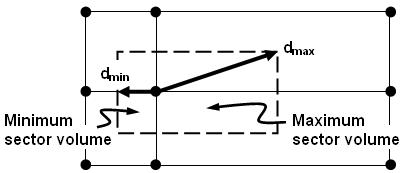
The most relevant measure of mesh expansion for the CFX-Solver is illustrated below. It involves the ratio of the maximum to minimum distance between the control volume node and the control volume boundaries. Because this measure is relatively expensive to calculate for arbitrarily shaped control volumes, an alternative formulation, the ratio of maximum to minimum sector volumes, is used.
This measure and its acceptable values are tabulated below, along with a measure that is available through the CFD-Post postprocessor. Values outside of the suggested acceptable range will increase sources of error that are due to the discretization of transient and body force terms.
|
Mesh Expansion Measure |
Acceptable Range |
Description and Notes |
|---|---|---|
|
Mesh Expansion Factor |
<20 |
Ratio of largest to smallest sector volumes for each control volume |
|
Element Volume Ratio (CFD-Post) |
<20 |
Ratio of largest to smallest element volumes that surround a node |
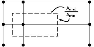
The concept of the mesh aspect ratio relates to the degree that mesh elements are stretched. The most relevant measure of aspect ratio for the CFX-Solver is illustrated below. It involves the ratio of the maximum to minimum integration point surface areas in all elements. Nodal (that is, control volume) values are calculated as the maximum of all element aspect ratios that are adjacent to the node.
The area based measure is tabulated below along with another measure that is available through the CFD-Post postprocessor. Values outside of the suggested acceptable range will lead to round-off errors and associated difficulties converging the discretized equations.
|
Mesh Aspect Ratio Measure |
Acceptable Range |
Description and Notes |
|---|---|---|
|
Aspect Ratio |
<100[a] |
Largest ratio of maximum to minimum integration point surface areas for all elements adjacent to a node |
|
Edge Length Ratio (CFD-Post) |
<100 |
Largest ratio of maximum to minimum integration edge lengths for all edges of element faces that touch a node |
[a] The acceptable range for both measurements is less than 1000 if running double precision.