


The Individual Component Initialization view contains the following tabs:
The Definition tab is used to specify:
The hub, shroud, inlet, and outlet curves and other regions for a turbo component (such as a rotor or stator). For details, see Turbo Regions Frame.
The parameters controlling the component’s associated background mesh.
The background mesh is a mesh generated on a constant-Theta projection of the passage, used to define spanwise and meridional coordinates for the 3D geometry. For details, see Background Mesh Frame.
The Turbo Regions frame is used to assign
2D regions to the Hub, Shroud, Blade, Inlet, Outlet, and Periodic regions of a
turbo component. These regions are not always required, but when provided,
may be used in the following ways:
The
Bladeregion specification is used to enable macros and plots that deal with blades (for example, a blade loading macro).The intersections of the
Hub,Shroud,InletandOutletregions withPeriodic 1may be used in order to generate internal polylines that are then collapsed in the Theta direction to form the boundaries of the background mesh. Alternatively, or if any of these intersections are not possible, polylines/lines may be specified explicitly in the Background Mesh frame. For details, see Background Mesh Frame.
In the special case of a turbo component that wraps 360 degrees around the rotation axis, there may be no periodic regions available. In this case, you may do one of the following:
Select the 360 Case Without Periodics check box.
Specify the hub, shroud, inlet, and outlet regions. Create a rectangularly-bounded slice plane, using the point-and-normal method, such that it intersects the turbo component on only one side of the rotation axis. In this case, it may be helpful to temporarily set the plane type to
Sampleso that you can see the entire plane. After the plane is in the correct position, set the type toSlice. Finally, specify this slice plane asPeriodic 1. You do not need to setPeriodic 2.Specify polylines for the hub, shroud, inlet, and outlet in the Background Mesh frame (described next).
In order to calculate Streamwise Location ( ) and Span coordinates for a
turbo component, a separate 2D mesh is created as an intermediate
step. The mesh, here referred to as a background mesh, is formed by taking the 3D passage boundaries (hub, shroud, inlet,
outlet) and collapsing them in the Theta direction, forming a 2D passage
outline on an axial-radial plane. The outline is then filled in with
a mesh consisting of lines of constant span and meridional coordinate.
The resulting mesh is then used to associate Streamwise
Location and Span coordinates with
any 3D position in the passage.
) and Span coordinates for a
turbo component, a separate 2D mesh is created as an intermediate
step. The mesh, here referred to as a background mesh, is formed by taking the 3D passage boundaries (hub, shroud, inlet,
outlet) and collapsing them in the Theta direction, forming a 2D passage
outline on an axial-radial plane. The outline is then filled in with
a mesh consisting of lines of constant span and meridional coordinate.
The resulting mesh is then used to associate Streamwise
Location and Span coordinates with
any 3D position in the passage.
The background mesh frame requires you to specify how the hub, shroud, inlet, and outlet curves will be obtained. The two available options are:
From Turbo RegionWhen
From Turbo Regionis specified for a particular curve, that curve is automatically extracted by intersecting the corresponding turbo region (specified in the Turbo Regions frame) with the specified Periodic 1 region (also specified in the Turbo Regions frame).From LineWhen
From Lineis specified for a particular curve, you must provide a polyline/line locator for that curve. You must use the latter method for every curve that cannot be derived by the first method (for example, because one or more Turbo Regions are not specified).
A line or polyline used to generate a background mesh must follow the entire surface it represents (along the component). One way in which a polyline can be created is by using the intersection between a bounded plane (such as a slice plane or a turbo surface of constant Theta) and the appropriate surface (for example, the hub surface). Before the polyline is used for initialization, is transformed by adjusting all Theta coordinates to the same value. The Theta coordinates of the polyline, therefore, have no effect; polylines obtained by intersection with a plane need not use a constant-Theta plane. If you cannot form the polyline easily, you can save pieces of the polyline to a series of files, use an editor to consolidate the parts, and then reload the edited file. For details, see:
Two methods are offered for creation of the background mesh:
LinearQuasi Orthogonal
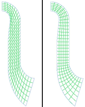
The figure on the left shows a background mesh (for clarity, Density was set to 200) using the Linear method, while the figure on the right shows the
mesh using the Orthogonal (default) method. As
can be seen from pictures, the Quasi Orthogonal method offers a higher-quality meridional space representation,
especially in highly curved passages.
Instancing settings are used to display multiple instances of objects. For example, if there are two turbo components, with the instancing information for component 1 specifying one copy, and the instancing information for component 2 specifying ten copies, then a turbo surface of constant span that covers both components will show, by default, one copy of the portion generated for component 1, and ten copies of the portion generated for component 2.
The Instancing tab for a turbo component is the same as the Instancing tab for a domain (see Instancing Tab) and similar to the Definition tab for an Instance Transform object (see Instance Transform: Definition Tab). (The Definition tab for an Instance Transform object is different in that its Axis Definition settings and Instance Definition settings cannot be set from a results file.)
By default, the Axis Definition and Instance Definition settings are automatically determined
from the results file. To set your own axis definition, set Axis Definition to Custom. To set
your own instance definition, set Instance Definition to Custom.
The instancing information specified for a component applies to graphic objects (or parts thereof) generated over the component. In order for this instancing information to apply to a graphic object:
At least part of the graphic object must be generated using data from the component (that is, there must be an association between the graphic object and the component).
The graphic object must have Apply Instancing Transform selected and Transform set to an Instance Transform that has Instancing Info From Domain selected.
The instancing information for a component is the same as the instancing information for the component’s domain, and the instancing information for any other component in the same domain.