


The tether element Cartesian coordinate system (TEA), Txyz, is defined as shown in Figure 10.1: Tether Element Axes and Nodal Displacement.
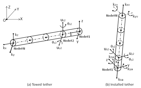
As shown in Figure 10.1: Tether Element Axes and Nodal Displacement (a), a towed tether initially lies in the horizontal plane of the fixed reference axes (FRA), and the TEA x-axis coincides with the zero current wave direction. The node sequence numbers along the tether increase with positive x-value, where the first node, at the trailing end of the tether, lies at the TEA origin.
For an installed tether, shown in Figure 10.1: Tether Element Axes and Nodal Displacement (b), the TEA is parallel to the global if the tether is vertical. Otherwise, in general, the TEA x-axis goes from the anchor node to the vessel attachment node, the y-axis direction is perpendicular to the TEA x-axis in the XY plane of the fixed reference frame, and the z-axis follows the right-hand rule. The TEA origin is at the anchor node.
The tether local axes (TLA) is introduced for data input and results output:
For a towed tether, the TLA is the same as the TEA.
For an installed tether, the TLA x-, y-, and z-axes are in the TEA y-, z-, and x-axes directions.
As the displacements along the tether are rotations and translations at each node, the nodal displacement vector of the j-th element in the tether element axes can be expressed as
 | (10–1) |
An 8×2 cubic shape function matrix is employed to define the displacement at the point (x, 0, 0) along the j-th tether element in the tether element axes, i.e.
 | (10–2) |
where  , in which
  is the length of this element.
Using this shape function, the structural mass matrix of the tether elements is defined by an 8×8 matrix as follows:
 | (10–3) |
where  is the structural mass per unit length.
The added mass for completely submerged tether elements will be the same as above, where the mass per unit length will be equal to the displaced mass per unit length. However, for partially submerged elements, the added mass is calculated by integrating the following function along the submerged length by a Gaussian integration scheme, such as
 | (10–4) |
where  is a diagonal 2×2 matrix of added mass per
unit length, which depends on the level of submersion of the tether
element:
is a diagonal 2×2 matrix of added mass per
unit length, which depends on the level of submersion of the tether
element:
 | (10–5) |
The structural stiffness matrix is given by:
 | (10–6) |
where  is the Young's modulus of elasticity
and
is the Young's modulus of elasticity
and  is the second moment of cross-sectional area.