


Morison’s equation for the fluid forces acting on the cross section of a slender structural member is
 | (6–1) |
where  is the drag coefficient,
  is the characteristic drag diameter,
  is the transverse directional fluid particle velocity,
  is the transverse directional structure velocity,
  is the inertia coefficient, and
  is the cross-sectional area.
The inertia coefficient and the drag coefficient are estimated empirically and are influenced by several parameters including Reynolds number, Keulegan-Carpenter number and others. The Reynolds number effect on the tube drag coefficient can be considered in Aqwa and is discussed in the next chapter.
In practice, the inertia coefficient and the drag coefficient
of a normal sized cylindrical tube could be approximated as 2.0 (or  ) and 0.75 respectively.
For a single side disc, the default values of inertia coefficient
and drag coefficient could be 2.4 (or
) and 0.75 respectively.
For a single side disc, the default values of inertia coefficient
and drag coefficient could be 2.4 (or  ) and 1.14 respectively. For a
non-cylindrical tube, these coefficients could be dependent on the
cross section directions.
) and 1.14 respectively. For a
non-cylindrical tube, these coefficients could be dependent on the
cross section directions.
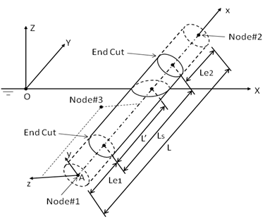
As shown in Figure 6.1: Local Tube Axis System, a tube local axis frame is used to define these directional dependent variables. In this right handed local axis frame, the origin A is located on the first node of the element, the local x-axis points towards the second node. For a non-cylindrical tube, the third node is away from the local x-axis and located on the local Axz plane. For a cylindrical tube, the local y-axis is in the global horizontal plane at right angle to the local x-axis, the local z-axis is orthogonal to the local x-y plane with z component in positive Z-direction; for a special case when the local x-axis is parallel to the global Z-axis, the local y-axis will be in the same direction as the global Y-axis.
Optionally, end-cuts ( ) are
used to leave gaps between the exposed ends and the nodes of tube
element. These end-cut parts will not contribute on the tube structural
mass and moment of inertia, and have no effect on the tube hydrostatic
and hydrodynamic properties. For a fully submerged case, the submerged
length of this tube element will be
) are
used to leave gaps between the exposed ends and the nodes of tube
element. These end-cut parts will not contribute on the tube structural
mass and moment of inertia, and have no effect on the tube hydrostatic
and hydrodynamic properties. For a fully submerged case, the submerged
length of this tube element will be  . For a partially submerged tube
case, the submerged tube length
. For a partially submerged tube
case, the submerged tube length  is the distance
between the center of the cross-water surface section and the end
cut of the submerged node, as shown in Figure 6.1: Local Tube Axis System.
is the distance
between the center of the cross-water surface section and the end
cut of the submerged node, as shown in Figure 6.1: Local Tube Axis System.
The hydrodynamic forces and moments are calculated first with reference to the local tube axis system by the integration of the cross sectional force/moment over the submerged length of L’,
 | (6–2) |
in which the hydrodynamic moments are with respect to the first node of the tube element, the subscripts y and z indicate the coefficients and velocity components in the y- or z-direction respectively.
In general a partially submerged tube which is arbitrarily inclined may have a section which is either completely submerged, partially submerged, or completely out of the water. Hence the integration in Equation 6–2 will be only over the submerged part.
In Aqwa, a three-point Gaussian integration scheme is employed to estimate the integral forms given by Equation 6–2. To ensure the accuracy of the numerical calculation of the tube force and moment, it is required that the tube element length be short enough. Following the general principle for the diffracting panel size requirement discussed in Mesh Quality Check, the tube element size should preferably be less than 1/7th of the shortest wavelength.
The forces and moments on each tube element are then transformed to the fixed reference axes (FRA) and, in addition, the moments are with respect to the center of gravity of the structure. The total fluid load is the summation of forces on all the tube elements and the panel elements.