


It is numerically convenient to represent the liquid hydrostatic and hydrodynamic properties using the local internal tank axes, then to transfer them into the global reference axes where the values are with respect to the combined center of gravity of mass of the structure and the liquid in the internal tanks. There may be several internal tanks on a marine structure; therefore multiple local internal tank axes could be introduced to refer to the individual tanks respectively.
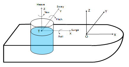
Figure 3.3: Local Internal Tank Axes and Basic Motions shows the local internal tank axes (LTA) for an internal tank. The LTA origin is at the center of the internal tank liquid plane (the center of flotation), and the LTA x-, y-, and z-axes are parallel to the X-, Y- and Z- axes of the global reference axes (FRA) respectively. In the LTA, six basic motions of the internal tank are three translational motions in the LTA axis directions and three rotational motions about the LTA axes.
The internal tank structure would contain items such as stiffeners, web frame, etc., which
reduces the total volume occupied by the liquid. Permeability is the percentage of the empty
volume in that space and could be represented by a coefficient, μ, in the range of
 . The typical value for internal tanks is 0.95 or higher.
The area of the liquid plane inside a tank at the structure equilibrium position in still water is determined by
 | (3–21) |
where St
is the wetted surface of the tank, and  is the unit normal vector of the tank hull surface pointing inwards. A zero
value for the liquid surface area indicates the fully filled tank condition.
is the unit normal vector of the tank hull surface pointing inwards. A zero
value for the liquid surface area indicates the fully filled tank condition.
The LTA origin of a partially filled internal tank,  , is set to be at the center of floatation, with the horizontal location in the
FRA determined by
, is set to be at the center of floatation, with the horizontal location in the
FRA determined by
 | (3–22) |
For a fully filled tank case, the horizontal location of the LTA origin could be above the tank and along the vertical line across the center of the internal tank liquid volume.
The volume of the liquid in an internal tank can be determined by the integration over its wetted surface in the LTA,
 | (3–23) |
where  is the coordinate of the wetted surface point in the LTA.
The center of the liquid volume in the tank in LTA,  , is determined by
 | (3–24) |
The center of the liquid volume in the tank in FRA is given by  .
.
The combined center of gravity of the mass of the structure and the liquid in tanks at the equilibrium position in still water with respect to the FRA is defined by
 | (3–25) |
where m is the structure mass,  is the structural COG in the FRA, ρt
is the liquid density in a tank associated with this structure, and Σ
indicates the summation of all the internal tanks associated with the structure.
is the structural COG in the FRA, ρt
is the liquid density in a tank associated with this structure, and Σ
indicates the summation of all the internal tanks associated with the structure.