The maximum number of pulleys per pulley set is 2.
      2   5  7   11    16    21    26    31        41        51        61
    - --- -- ---- ----- ----- ----- ----- --------- --------- --------- ---------
   |X|   |  |PULY|     |     |     |     |         |         |         |         |
    - --- -- ---- ----- ----- ----- ----- --------- --------- --------- ---------
       |  |   |     |     |     |     |       |         |         |         |
       |  |   |     |     |     |     |       |         |         |         |_(9) Sliding Friction (T2/T1) (F10.0)
       |  |   |     |     |     |     |       |         |         |
       |  |   |     |     |     |     |       |         |         |_(8) Bearing Friction (T2/T1) (F10.0)
       |  |   |     |     |     |     |       |         |
       |  |   |     |     |     |     |       |         |_(7) radius (F10.0)
       |  |   |     |     |     |     |       |
       |  |   |     |     |     |     |       |_(6) angle (E10.0)
       |  |   |     |     |     |     |
       |  |   |     |     |     |     |_(5) Node Number (I5)
       |  |   |     |     |     |
       |  |   |     |     |     |_(4) Structure Number (I5)
       |  |   |     |     |
       |  |   |     |     |_(3) Node Number (I5)
       |  |   |     |
       |  |   |     |_(2) Structure Number (I5)
       |  |   |
       |  |   |_(1) Mooring Line Code (A4)
       |  |
       |  |_Optional User Identifier (A2)
       |
       |_Compulsory END on last data record in Data Category (A3)
(1) The PULY data record indicates that a pulley is positioned on a line. A maximum of 2 pulleys is allowed for each pulley set (i.e. two pulleys per LINE), with the first PULY data record following a LINE data record, i.e. applying to the most recently defined LINE. In the case of a 2 pulley set the second PULY data record will follow the first PULY data record. A PULY has the effect of intersecting a LINE and will effectively extend the LINE from the LINE's node to the second PULY node.
(2) This is the structure number to which the pulley is attached and must correspond to one of the structures defined in Data Category 2. If '1' is input, this will correspond to the structure defined in Data Category ELM1. If '2' is input, this will correspond to the structure defined in Data Category ELM2 etc. Note that Structure '0' (i.e. a fixed node) is an ILLEGAL structure and will produce an error (see (4)).
(3) This is the node number whose position is the attachment point of the pulley on the structure specified (1). The position of this node on the structure (2) must have been defined in Data Category 1. Items (2) & (3) must appear on the previous LINE data record (see examples).
(4)-(5) This structure number (4) and its corresponding node number (5) define the attachment position of the other end of the mooring line. The position of this node on the structure (4) must have been defined in Data Category 1.
If '0' is input as the structure number (4), together with a node number (5), the program will recognize that this node number (5) references a fixed position as defined in Data Category 1 in the Fixed Reference Axis System (FRA). Note that a non-zero structure number (4) must be followed by a valid node number (5) on that structure.

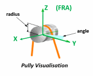
(6) This value represents the angle at which the pulley lies about the Z axis (FRA). The default angle (0°) places the pulley in the orientation shown in the diagram.
(7) The radius is used to indicate the radius of the pulley, but is not used for the purpose of the calculation. The radius of the pulley will be displayed in the Aqwa Graphical Supervisor.
(8)-(9) There are two possible formulations for the friction. In each case the friction of the pulley is represented by T2/T1, where T2 is the larger tension and T1 the smaller. T2/T1 should be defined for the situation where the line turns through 180° around the pulley.
T2/T1 in columns 51-60 represents bearing friction of a pulley rotating around an axle
T2/T1 in columns 61-70 represents sliding between the rope and the pulley, for example if the pulley represents a fairlead.
If values are entered in both fields the first definition (bearing friction) overrides the second (sliding friction).
Pulley with bearing friction: a friction factor μ is calculated such that μ = (T2-T1) / (T2+T1). The friction is then varied depending on how far around the pulley the line passes.
Pulley with sliding friction: a friction factor μ is calculated such that (T2/T1) = exp(μπ). The friction is then varied depending on how far around the pulley the line passes.
In each case T2/T1 must be in the range 1 ≤ T2/T1 ≤ 2.
Pulleys - Assumptions and Restrictions
A PULY data record must be preceded by a LINE data record.
Maximum of 2 pulleys per pulley set.
The radius of the pulley is ignored for the purpose of the calculations.
If distance from start of pulley mooring line to end point is less than the total length, then the whole line is slack.
The pulley lines are assumed to be in contact with the pulleys at all times.
Distances between pulley points are assumed to be scalar quantities. For example, a structure may be 'drawn through' a pulley to appear on the other side.
Examples of Connectivity

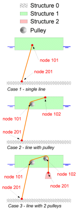
The following three cases demonstrate the required input of connectivity for systems including pulleys.
CASE 1 Is a standard LINE connected between a single structure and earth. The typical connectivity input for this system would be:
LINE 1 101 0 201 ...
CASE 2 Is a LINE connected between a single structure and earth. A pulley is inserted on the line and extends the line to node 102. The typical connectivity input for this system would be:
       LINE  1  101  0  201   ...
       PULY  1  101  1  102   ...
CASE 3 Is a LINE connected between a two structures and earth, with a 2 pulley set on the LINE. The typical connectivity input for this system would be:
       LINE  1  101  0  201   ...
       PULY  1  101  1  102   ...
       PULY  1  102  2  201   ...

