VM71
VM71
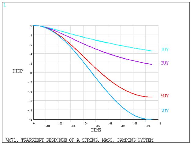
Transient Response of a Spring-Mass-Damper System
Test Case
A spring-mass system with viscous damping is displaced by a distance Δ and released. Determine the displacement u at time t for four damping ratios:
ξ = 2.0
ξ = 1.0 (critical)
ξ = 0.2
ξ = 0.0 (undamped)
| Material Properties | Loading | |||||
|---|---|---|---|---|---|---|
|
|
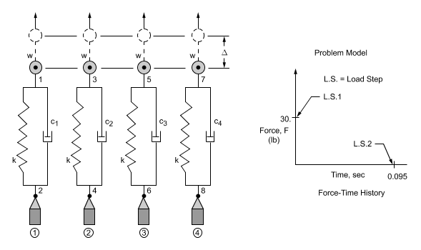
Analysis Assumptions and Modeling Notes
The initial static force is calculated as kΔ = 30 lb and
the damping coefficients are calculated as c = 2ξsqrt(km) = 3.52636,
1.76318, 0.352636, and 0.0 lb-sec/in for the four damping ratios
(ξ) given in the test case, respectively. The node locations are
arbitrarily selected. The integration time step (0.001 sec) is based
on
 1/180 of the period to allow the
step changes in acceleration to be followed reasonably well and to
produce sufficient printout for the theoretical comparison. The maximum
time of 0.095 sec covers about 1/2 the period. A static solution is
done at the first load step. POST26 is used to extract results from
the solution phase.
1/180 of the period to allow the
step changes in acceleration to be followed reasonably well and to
produce sufficient printout for the theoretical comparison. The maximum
time of 0.095 sec covers about 1/2 the period. A static solution is
done at the first load step. POST26 is used to extract results from
the solution phase.