VM37

VM37
Elongation of a Solid Bar

Overview

Reference:C. O. Harris, Introduction to Stress Analysis, The Macmillan Co., New York, NY, 1959, pg. 237, problem 4.
Analysis Type(s):Static Analysis (ANTYPE = 0)
Element Type(s):
3D Structural Solid Elements (SOLID45)
3D Structural Solid Elements (SOLID185)
3D Structural Solid Shell Elements (SOLSH190)
Input Listing:vm37.dat

Test Case

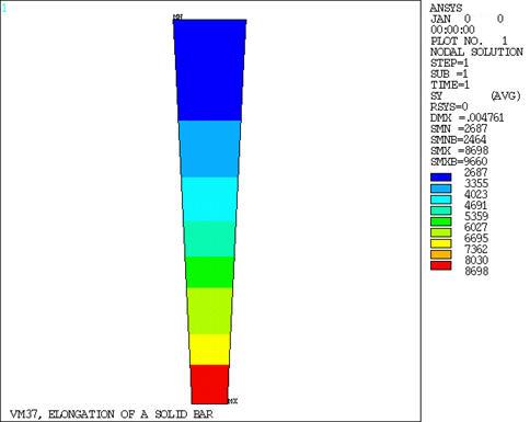
A tapered aluminum alloy bar of square cross-section and length L is suspended from a ceiling. An axial load F is applied to the free end of the bar. Determine the maximum axial deflection δ in the bar and the axial stress σy at mid-length (Y = L/2).

Figure 49: Solid Bar Problem Sketch

Solid Bar Problem Sketch

Material PropertiesGeometric PropertiesLoading
E = 10.4 x 10⁶ psi
υ = .3
L = 10 in
d = 2 in
F = 10,000 lb

Analysis Assumptions and Modeling Notes

The problem is solved in three different ways:

  • Using 3D Structural Solid Elements (SOLID95)

  • Using 3D Structural Solid Elements (SOLID186)

  • Using 3D Structural Solid Shell Elements (SOLSH190)

A single tapered volume is mapped-meshed with seven brick-shaped elements along the length of the bar.

POST1 is used to get the nodal displacements at the free end and the axial stress at mid-length of the bar.

Results Comparison

 TargetMechanical APDLRatio
SOLID45
d , in0.0048077.00475700.989
Stressy , psi (elem. 4)4444.4441.0880.999
SOLID185
d , in0.0048077.00475700.989
Stressy , psi (elem. 4)4444.4441.0880.999
SOLSH190
d , in0.0048077.00478010.994
Stressy , psi (elem. 4)4444.4463.291.004

Figure 50: Elongation of a Solid-Bar-Axial Stress Contour Display (SOLID45 Model)

Elongation of a Solid-Bar-Axial Stress Contour Display (SOLID45 Model)