


VM193
VM193
Evaluation of Stress Intensity Factor for an Inclined Crack Using XFEM
Method
Overview
| Reference: | Liu, X.Y., Ziao, Q.Z., and Karihaloo, B.L., "XFEM for direct evaluation of mixed-mode SIFs in homogenous and bi-materials", International Journal for Numerical Methods in Engineering, vol. 59, pp. 1103-1118, 2004 |
| Analysis Type(s): | Static Analysis (ANTYPE = 0) |
| Element Type(s): | 2D 4-Node Structural Solid (PLANE182) |
| Input Listing: |
vm193.dat
VM193 requires a supplemental .cdb input file which is too long to include full input listings. This file must be downloaded and placed in your working directory for the test case to run properly. Additionally, the geometry and mesh should be regenerated. Download link: MAPDL Test Case Files for 2024 R2
|


Test Case
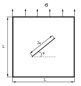
A 2D plate with length L is subjected to uniform tension loading. An inclined crack of
length 2a is modeled with 4 different angles,  ,
,  ,
,  , and
, and  . The singularity-based XFEM method is used to account for crack tip singularity
effects. Stress intensity factors for each case are computed using
CINT,TYPE,SIFS.
. The singularity-based XFEM method is used to account for crack tip singularity
effects. Stress intensity factors for each case are computed using
CINT,TYPE,SIFS.
| Material Properties | Geometric Properties | Loading | |||||
|---|---|---|---|---|---|---|---|
|
|
 = 1 Pa = 1 Pa |


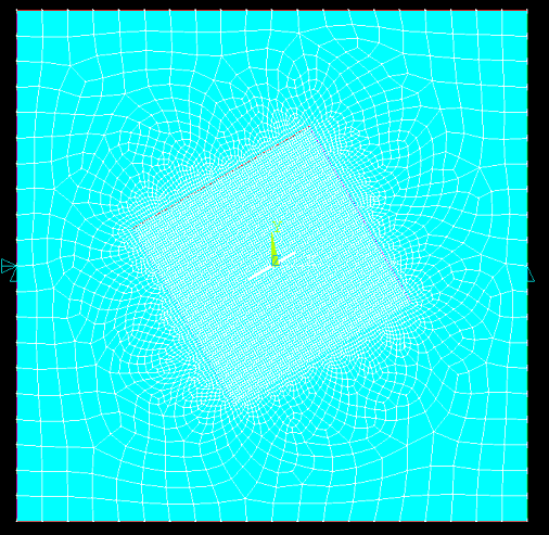
Analysis Assumptions and Modeling Notes
The problem is solved using 2D PLANE182 elements with plane stress element behavior. The plate is constrained along the X, Y direction at location X = -5 meters and Y = 0 meters, and along the Y direction at location X = 5 meters and Y = 0 meters. The 2 crack tip node components (CRKTIPELEM1 and CRKTIPELEM2) and the number of paths surrounding this crack tip are defined using the CINT command. Mode 1 (K1) and Mode 2 (K2) stress intensity factors obtained from contours 2, 3, 4, 5, and 6 are then averaged and compared against the reference solution.
Results Comparison
| Angle | Value | Tip Node Component | Target | Mechanical APDL | Ratio |
|---|---|---|---|---|---|
| 0° | K1 | CRKTIPELEM1 | 1.253 | 1.269 | 1.013 |
| CRKTIPELEM2 | 1.269 | 1.013 | |||
| K2 | CRKTIPELEM1 | 0.000 | 0.000 | 1.000 | |
| CRKTIPELEM2 | 0.000 | 1.000 |
| Angle | Value | Tip Node Component | Target | Mechanical APDL | Ratio |
|---|---|---|---|---|---|
| 30° | K1 | CRKTIPELEM1 | 0.940 | 0.951 | 1.012 |
| CRKTIPELEM2 | 0.951 | 1.012 | |||
| K2 | CRKTIPELEM1 | 0.543 | 0.556 | 1.025 | |
| CRKTIPELEM2 | 0.556 | 1.025 |
| Angle | Value | Tip Node Component | Target | Mechanical APDL | Ratio |
|---|---|---|---|---|---|
| 45° | K1 | CRKTIPELEM1 | 0.627 | 0.634 | 1.011 |
| CRKTIPELEM2 | 0.634 | 1.011 | |||
| K2 | CRKTIPELEM1 | 0.627 | 0.642 | 1.024 | |
| CRKTIPELEM2 | 0.642 | 1.024 |
| Angle | Value | Tip Node Component | Target | Mechanical APDL | Ratio |
|---|---|---|---|---|---|
| 60° | K1 | CRKTIPELEM1 | 0.313 | 0.316 | 1.011 |
| CRKTIPELEM2 | 0.316 | 1.011 | |||
| K2 | CRKTIPELEM1 | 0.543 | 0.556 | 1.023 | |
| CRKTIPELEM2 | 0.556 | 1.023 |