VM169
VM169
Permanent Magnet Circuit With an Air Gap
Overview
| Reference: | F. C. Moon, Magneto-Solid Mechanics, John Wiley and Sons, Inc., New York, NY, 1984, pg. 275. |
| Analysis Type(s): | Magnetic Field Analysis (ANTYPE = 0) |
| Element Type(s): | Tetrahedral Coupled-Field Solid Elements (SOLID98) |
| Input Listing: |
VM169 requires a supplemental .cdb input file which is too long to include full input listings. This file must be downloaded and placed in your working directory for the test case to run properly. Additionally, the geometry and mesh should be regenerated. Download link: MAPDL Test Case Files for 2024 R2 vm169.cdb |
Test Case
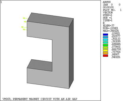
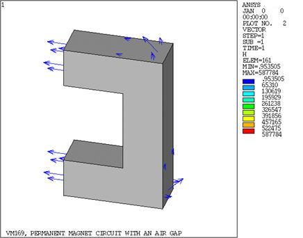
A permanent magnet circuit consists of a highly permeable core, a permanent magnet (the darker shading in the sketch), and an air gap. Assuming an ideal circuit with no flux leakage, determine the magnetic flux density and field intensity in the permanent magnet and the air gap.

| Material Properties | Geometric Properties | ||||||||
|---|---|---|---|---|---|---|---|---|---|
|
|
Analysis Assumptions and Modeling Notes
The problem is solved using coupled-field solid elements (SOLID98). The permanent magnet is polarized along a line at Θ = -30° to the Z-axis in the X-Z plane. The coercive force components are calculated as MG169 = Hc cos Θ = 129,900, MGZZ = Hc sin Θ = -75,000. The permanent magnet relative permeability, μr, is calculated as:

The iron is assumed to be highly permeable and is assigned a value μr = 1 x 10⁵.
Since the device is symmetric only half of the circuit is required for modeling. At the symmetry plane the flux lines are orthogonal, so a flux-normal (Φ = 0) boundary condition is applied. With no leakage in the system, all the flux flows along a path circumventing the circuit. The flux-parallel boundary condition (δ Φ / δn = 0) holds on all other surfaces. The Reduced Scalar Potential (RSP) strategy is selected (default) since no current sources are defined. POST1 is used to extract results from the solution phase.
Results Comparison
| Using SOLID98 | Target | Mechanical APDL | Ratio |
|---|---|---|---|
| |B|, T (perm. magnet) | .7387 | .7387 | 1.000 |
| |H|, A/m (perm. magnet) | 39150 | 39207.5541 | 1.001 |
| |B|, T (air gap) | .7387 | .7386 | 1.000 |
| |H|, A/m (air gap) | 587860 | 587791.6563 | 1.000 |