VM163
VM163
Groundwater Seepage (Permeability Analogy)
Test Case
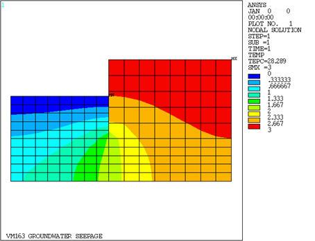
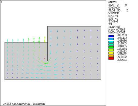
An opened top and bottom circular steel caisson separates a low level excavation from the surrounding ground. Determine the groundwater seepage flow rate q beneath the caisson for fully saturated soil. The pressure head is T1 with respect to a datum To at the bottom of the caisson. Show the pressure contours and the flow path.

| Material Properties | Geometric Properties | Loading | |||||||
|---|---|---|---|---|---|---|---|---|---|
|
|
|
Analysis Assumptions and Modeling Notes
The thermal analysis, which solves the Laplace equation, is used to solve this problem since the seepage flow is also governed by the Laplace equation. The following mental substitution of input and output variables (thermal : flow) are used:
(temperature : flow potential (or pressure head))
(heat flow rate : fluid flow rate)
(thermal conductivity : permeability coefficient)
The bottom and side of the model are assumed to be far enough away from the caisson to be treated as impermeable.