VM100
VM100
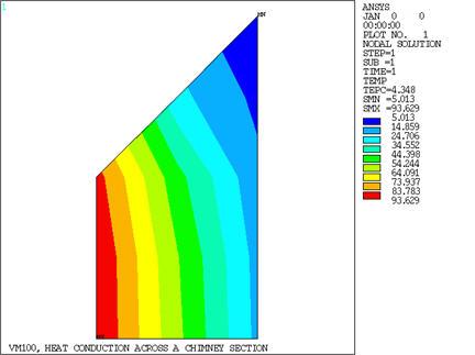
Heat Conduction Across a Chimney Section
Test Case
Determine the temperature distribution and the rate of heat
flow q per foot of height for a tall chimney whose cross-section is
shown in Figure 140: Heat Conduction Across a Chimney Section Problem Sketch. Assume that the inside gas
temperature is Tg, the inside convection coefficient
is hi, the surrounding air temperature is Ta, and the outside convection coefficient is ho.
Analysis Assumptions and Modeling Notes
Due to symmetry, a 1/8 section is used. The finite element
model is made the same as the reference's relaxation model for a direct
comparison. The solution is based on a fin of unit depth (Z-direction).
POST1 is used to obtain results from the solution phase.
Results Comparison
Based on a numerical relaxation
method.
From heat rates at elements
1 and 3 multiplied by 8.